
1.7. Git and GitLab (2026)
1.7. Git and GitLab (2026)
Introduction
This tutorial addresses the use of Git and Gitlab together with STM32CubeIDE.
Polytech students must get a clear understanding of the following, because Gitlab will be massively used in the future to evaluate their progress. For others, if not interested, you may just skip this tutorial.
What is Git?
"Git is a version control system for tracking changes in computer files and coordinating work on those files among multiple people. It is primarily used for source code management in software development, but it can be used to keep track of changes in any set of files. As a distributed revision control system, it is aimed at speed, data integrity, and support for distributed, non-linear workflows." Source : https://en.wikipedia.org/wiki/Git
In these tutorials, we will use a single sandbox project my_projet that will grow as you experiment with new STM32 peripherals or new hardware/software mechanisms. Git will be used to take snapshots (current project state) of your progress along the way. Far from a proper Git introduction, here are the few things you need to know.
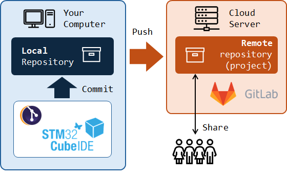
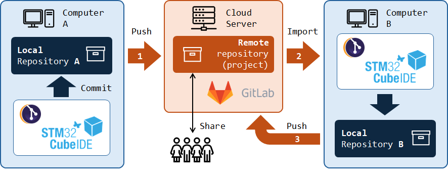
Together with Git, comes the idea of repositories. A repository is simply a file location where changes in you project files are tracked and recorded. Usually you'll have to deal with 2 repositories:
A local repository. It is located on your computer. The basic operation of recording the changes in your project files to that repository is called a Commit action.
A remote repository. It is located on the network. It is used to share project progress with other developers and therefore allows for collaborative developments. The basic operation of synchronizing the remote repository from the local repository is called a Push action. Remote Git repositories are hosted by servers either on the cloud or on local networks. Well known platforms are GitHub and GitLab. We will use a private GitLab instance, installed on a school server.
A Commit is also the name given to the snapshot resulting from the commit action at a given point in time. In a regular development process, the committing strategy is up to you. You do not need to commit every time you make small changes. You would rather commit when you feel like current project version reached a state that deserve a dedicated archive before you go further. It is a kind of a milestone.
1. GitLab
GitLab is a web-based Git repository manager (see https://about.gitlab.com).

The Polytech GitLab instance is available here : https://gitlab.polytech.umontpellier.fr
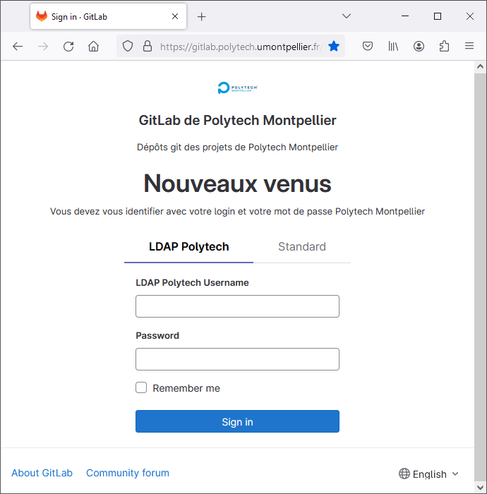
You should be able to connect with your Polytech regular login/password.
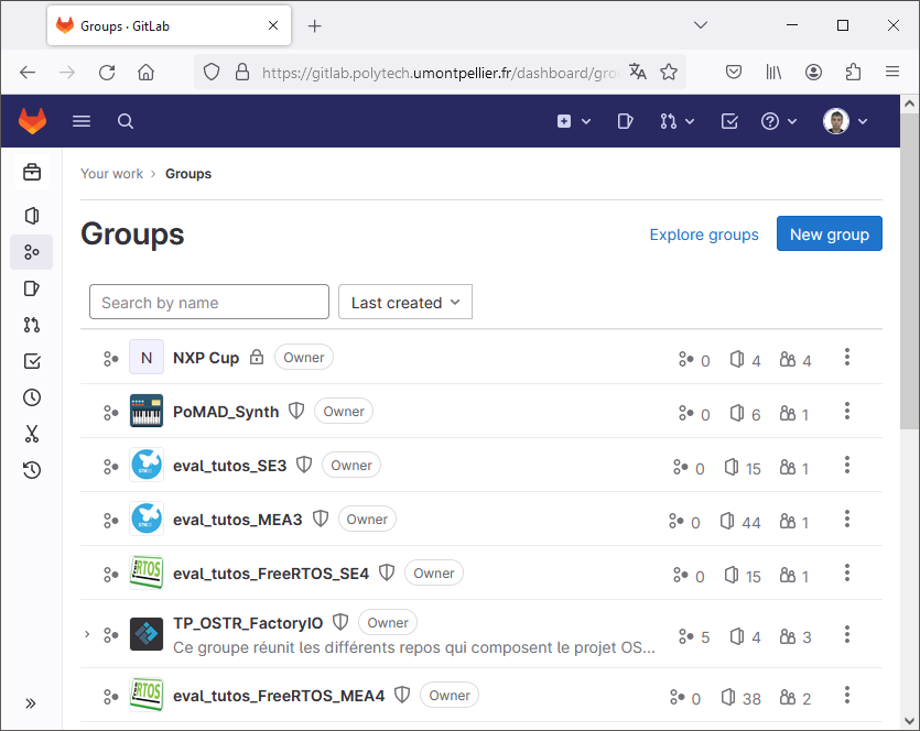
From there, you can browse existing Groups and Projects, either yours or other's, that have been made available to the world, or to local users.
2. Git integration with STM32CubeIDE
On Mac and Linux computers, Git is natively supported. You can therefore perform Git operations, locally or on the remote server, using command line interface (CLI) from any terminal. On Windows, you can install Git for Windows software (https://gitforwindows.org/) to make such things available using the gitbash terminal. Don't do it now unless you're willing to learn Git commands (which would not be a bad idea anyway, but not necessary for now).

In these tutorials, we're not going to use direct commands but an Eclipse Git plugin instead. It provides a simple graphical interface approach to using Git and remote servers to archive your project, track changes in source code, and collaborate with other developers.
At time of writing, STM32CubeIDE does not come with a ready to use Git plugin, but it is pretty easy to install.
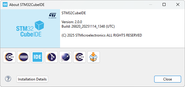
Before that, let us check what software and plugins are actually installed. From the main menu, go to Help → ![]() About STM32CubeIDE
About STM32CubeIDE
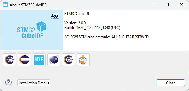
If the About dialog displays the ![]() Eclipse EGit module here, you can probably skip the next steps as EGit is already installed. If you have a fresh STM32CubeIDE install, that should not be the case.
Eclipse EGit module here, you can probably skip the next steps as EGit is already installed. If you have a fresh STM32CubeIDE install, that should not be the case.
Click Installation Details and review installed packages. In the example below, no external plugins have been installed apart from those included with STM32CubeIDE.
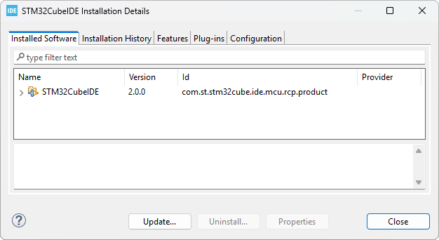
Close Details and the About dialog.
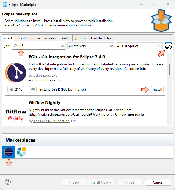
Open Help → ![]() Eclipse Marketplace...
Eclipse Marketplace...
In the Marketplaces area, make sure Eclipse Marketplace is selected
In the Find field, enter "egit"
Click the Go button to start searching the Marketplace
When the EGit plugin is found, click Install.
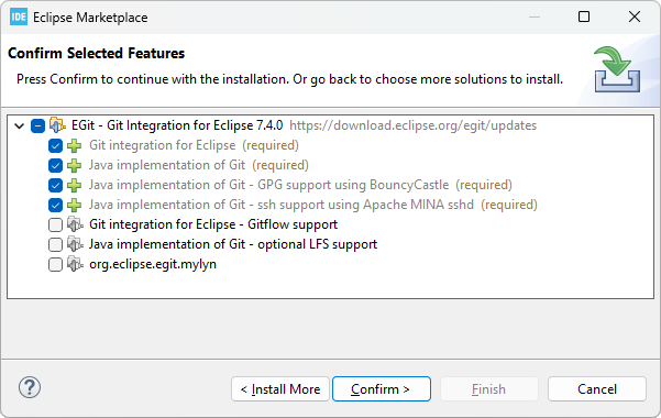
In the next dialog, just leave default selected features and then Confirm >.
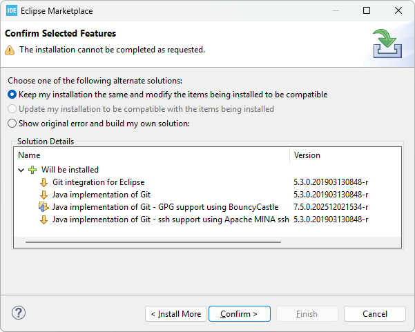
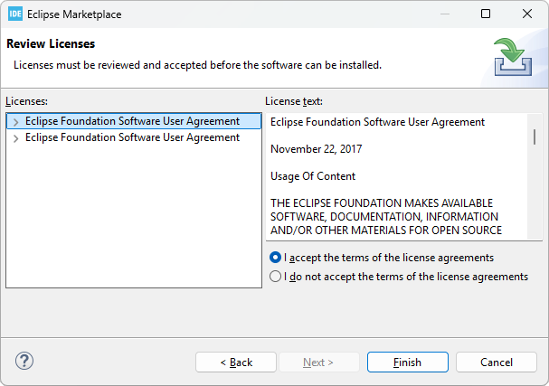
Eclipse will check dependencies and you may be asked to confirm some adjustments:
Accept the license agreement and Finish.
It will take a little while for the plugin to install. You can monitor the progress in the IDE status bar (Window→Appearance→Show Status Bar).
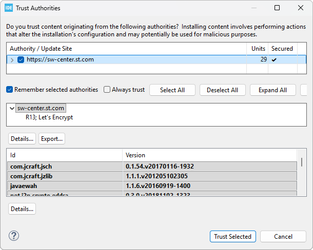
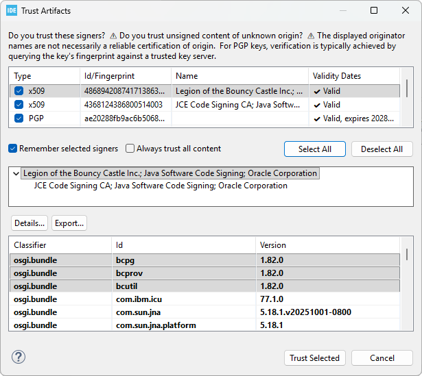
You will be asked to trust authorities and artifacts along the way.
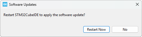
When done, you'll be asked to restart Eclipse.
After restarting the IDE, go back to Help → ![]() About STM32CubeIDE. You should see the Eclipse EGit module now added:
About STM32CubeIDE. You should see the Eclipse EGit module now added:
Close Details and the About dialog.
3. Creating a local repository
Now EGit is installed, let us create a local repository and use it for committing project files.
We're going to use the blink project for these experimentation. Let us leave my_project apart since it will be the starting point for the "real" thing coming next...
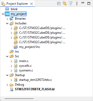
In the Project Explorer, close all projects and open blink.
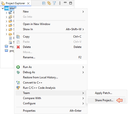
Right-click blink folder and select Team → Share Project...
First step consists in configuring the local Git Repository, that will keep track of code change history on your computer. Although this is not recommended, a simple choice is to have a local repository for each individual project. For that, just select Use or create repository in parent folder of project, then select the project name, and finally click the Create Repository button.
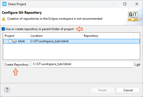
When done, click Finish.
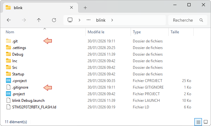
If you take a look into the project folder, you will notice that a new \.git folder has appeared. It is your local repository. There's also a .gitignore file that is new. This file contains a list of directories and files which are not concerned by Git tracking. Basically, you'll find here the \Debug project folder that contains no source code, and is re-generated each time you build the project. Do not edit the .gitignore file.
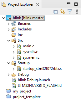
You'll also notice that the project appearance in the Project Explorer has somehow changed:
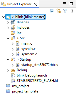
You can get documentation on EGit icon overlays here. For quick reference, the legend below provide a first level of information:
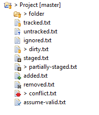
According to the above, project files appear at the moment as '?' untracked.
And finally, you’ll see that the contextual Team menu is now populated with a lot of new possible actions:
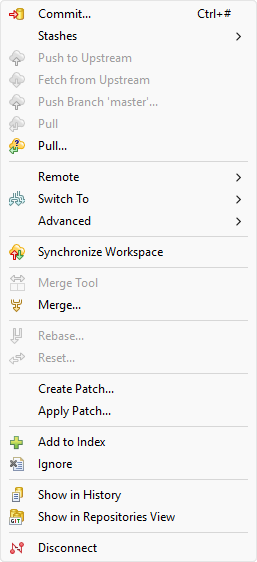
The ![]() Disconnect command deletes the .git folder (local repository) and completely dissociate the project from any Git history, thus restoring the initial situation. It is useful for instance when you import "gited" project that you want to disconnect from previous records and associated repositories.
Disconnect command deletes the .git folder (local repository) and completely dissociate the project from any Git history, thus restoring the initial situation. It is useful for instance when you import "gited" project that you want to disconnect from previous records and associated repositories.
4. First Commit
The Commit action is used to save your project changes to the local Git repository. For a project that was never committed before, well, everything is considered as changes.
From the blink contextual menu select Team → ![]() Commit...
Commit...
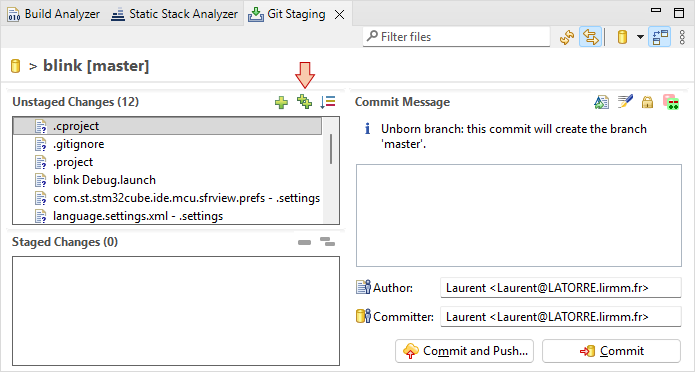
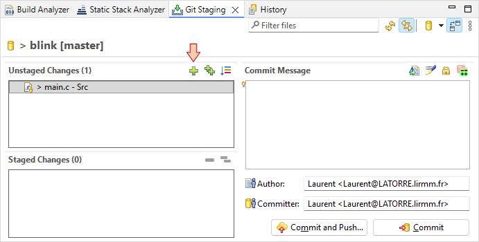
In the ![]() Git Staging panel that opens, the Unstaged Changes area lists all the files that have changed since last commit, i.e. all the source and project files here. All these files should be under Git tracking. Add all the files to the Staged Changes area by clicking the
Git Staging panel that opens, the Unstaged Changes area lists all the files that have changed since last commit, i.e. all the source and project files here. All these files should be under Git tracking. Add all the files to the Staged Changes area by clicking the ![]() button. Alternatively, you can select all of them (CTRL-A) and manually drag them into the Staged Changes field.
button. Alternatively, you can select all of them (CTRL-A) and manually drag them into the Staged Changes field.
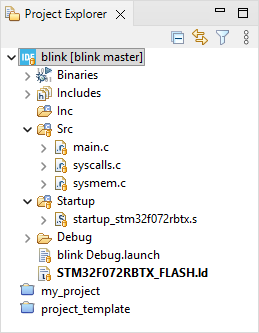
At this moment, you may observe that icons in the Project Explorer have changed, now signaling folders as '*' staged and files as '+' added to the tracking process.
Then enter a Commit Message (mandatory) which describes the purpose of committing.
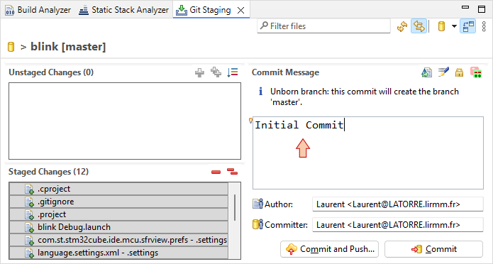
Then, click the ![]() Commit button. Again, Project Explorer items look different. Actual display means that current project files and folders are in sync (tracked) with the local Git repository information (i.e. no file has been modified since last commit).
Commit button. Again, Project Explorer items look different. Actual display means that current project files and folders are in sync (tracked) with the local Git repository information (i.e. no file has been modified since last commit).
Congratulations, you've successfully performed your fist commit!
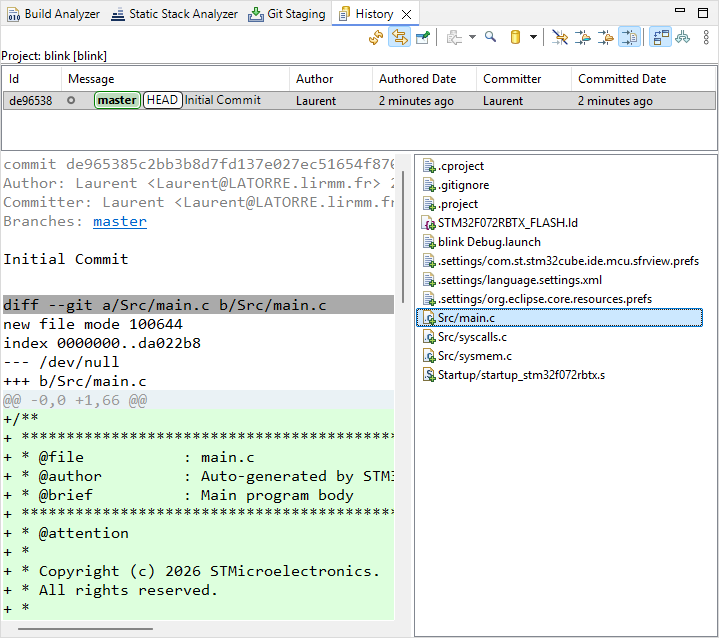
You can review commit properties by selecting Team → ![]() Show in History
Show in History
5. Keeping track of code changes
You remember that, since we changed clock settings, the blink3 demo now blinks very fast.
Edit the main() function and double the delay during the ON state of the LED:
#define DELAY_ON	40000		// Longer delay during ON state (was 20000)
#define DELAY_OFF	100000
Save ![]() main.c, build
main.c, build ![]() the project and run
the project and run ![]() the application to verify that you obtain the expected effect on the LED blinking (slower blinking).
the application to verify that you obtain the expected effect on the LED blinking (slower blinking).
notice that the change in main.c has been detected and it is now flagged as '>' dirty. That only means that the file main.c is no more in sync with the repository.
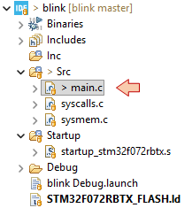
main.c is now candidate for staging.
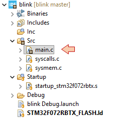
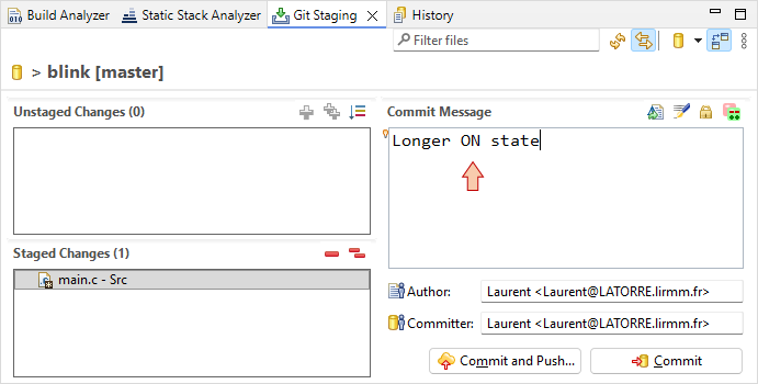
Drag main.c into the Staged Changes area and observe the Project Explorer. Now main.c is flagged as '*' staged.
Provide a Commit Message (e.g. 'Longer ON state') and then click the ![]() Commit button.
Commit button.
You can then use the History panel, and select the commit and file your want to review:
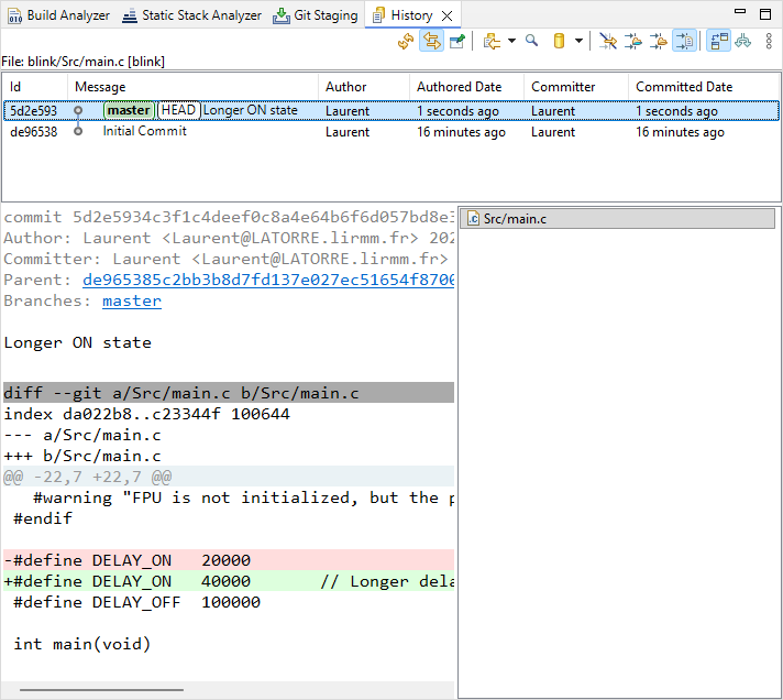
6. Remote Push to GitLab repository
Next step is to Push the local repository into a remote repository on GitLab. To do that, we need:
- To create SSH key pair (private/public) to authenticate the communication between your computer and GitLab
- To register/associate the public part of SSH key with your GitLab account
- To create the remote repository via the GitLab web interface
- To configure the remote repository within EGit
- To perform the Push action
Let's go!
6.1. Creating SSH key pair
In order to have your computer working with GitLab, we must first setup an authentication mechanism which links your computer session to your GitLab account with high level of security. This is done by means of a SSH-RSA key pair (public/private). Note that this authentication method is not specific to STM32CubeIDE.
The first step is to generate a random SSH key pair (public/private) and to store those keys somewhere well identified on your computer. You can use any software tool able to generate SSH keys. On Mac, Linux and Windows, the ssh-keygen command is available from the console. You may also use PUTTYgen if you're after a standalone GUI solution.
The common location (path) to where SSH keys are store is a .ssh folder at the root of the user home directory:
C:\Users\<username>\.ssh (Windows)
/home/<username>/.ssh (Linux)
You may want to check if you don't already have such keys before you proceed creating new ones. Let us assume you have no SSH keys.
Open a command terminal (cmd on windows) and type:
> ssh-keygen -t rsa -b 1024
You will be prompted to choose a destination folder. In the example below, we just leave options to their default values (just pressing Enter):
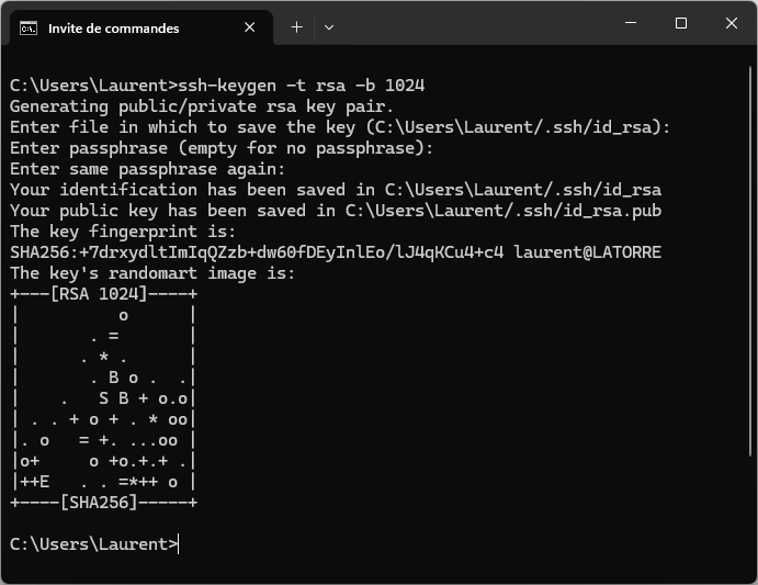
Then make sure that the two keys have been generated:
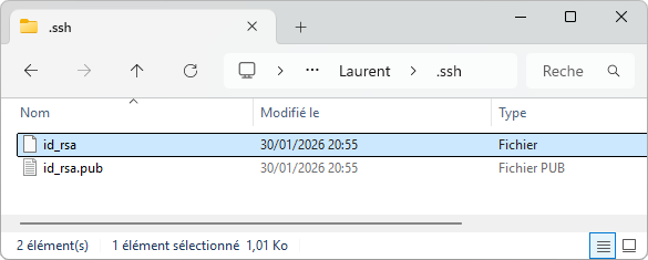
If you're using your own computer the default path is OK. When using school computers, you should store the SSH keys to your network user folder (e.g. P:\.ssh). Doing so, you will be able to access GitLab from any workstation in the school when logged with your credentials.
Both keys are text files you can open with any text editor:
id_rsa_pub is the public key:
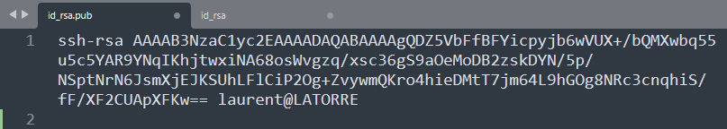
That's the part you need to register and associate to your GitLab account. Just copy (CTRL-A, CTRL-C) the whole file content into the clipboard for now.
id_rsa is the private key:
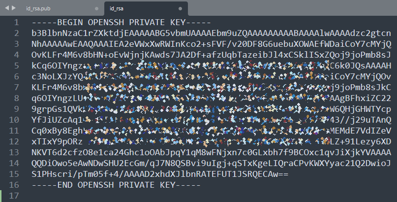
This part stays on your computer (or your private network drive).
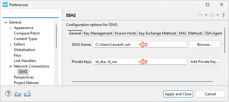
Wherever you store your SSH keys, you need to tell Eclipse where it is. For this, from the main menu select Window→Preferences, and select the General, Network Connections, SSH2 category. Then provide the path to your keys in the SSH2 Home field, and make sure that Private keys field include the id_rsa filename.
6.2. Registering your key within GitLab
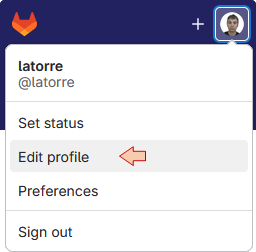
Log into GitLab web interface go to your user Settings and Edit profile:
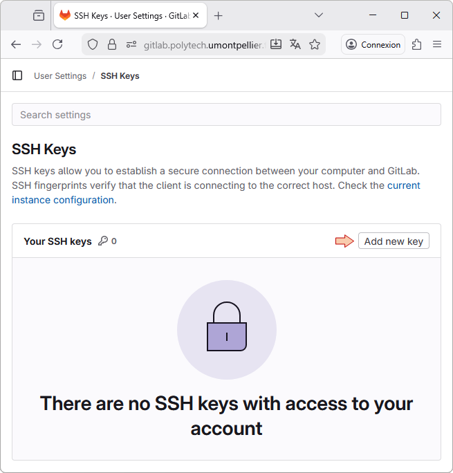
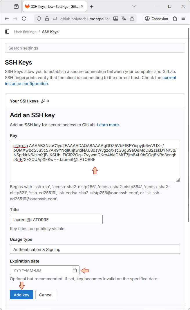
Then from the lateral left toolbar, select SSH Keys, and then the Add new key button.
In the Key field, paste the content of the public key you generated before. Provide a Title for the key that helps identifying the location it will authenticate. You also can remove any expiration date so that the key will never expires. Then press the Add Key button.
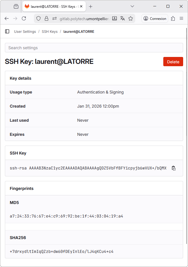
This will add associate new SSH key with your GitLab account. You should even get an email from GitLab saying so.
Going back to SSH Keys main window, you should see the newly created key:
You don't need to repeat the above steps for every project (key generation and registering). Now that you have a key, which is registered on your GitLab account, it can be used with any workspace or any project, even beyond STM32 programming and STM32CubeIDE. It is not attached to any particular software.
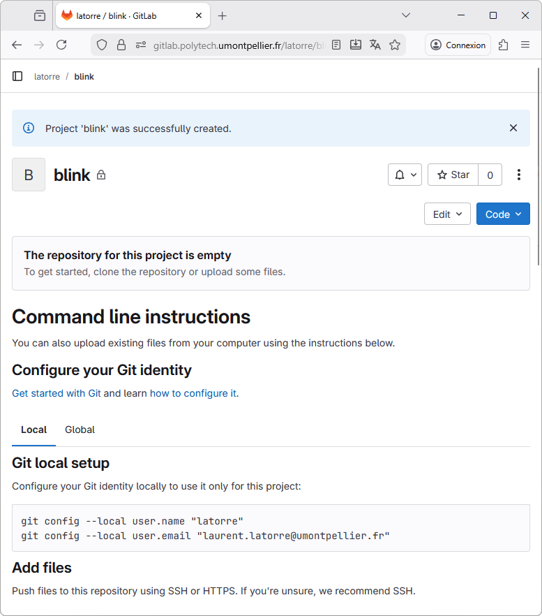
6.3. Creating a GitLab remote repository
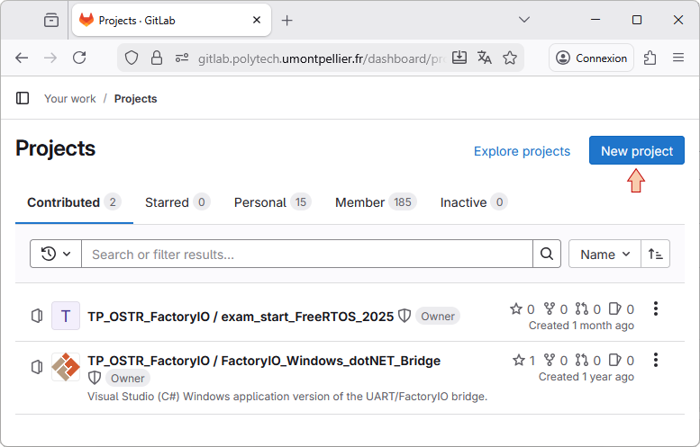
Still within GitLab web interface, and from the top toolbar, select Projects →Your Projects. Then click the New project button.
Choose Create blank project. You need to provide a name to the project. Although not mandatory, let-us give the same name as the STM32CubeIDE project we want to associate with this repository. You can choose which level of privacy you want. In any level of privacy, edits are only possible for project members only.
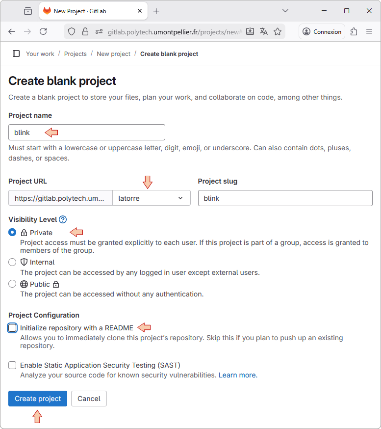
When you're done, click the Create project button.
You’ll end up with an empty new project as shown below. Leave this page open, but put the navigator window aside for the moment.
6.4. Configure the remote repository within EGit
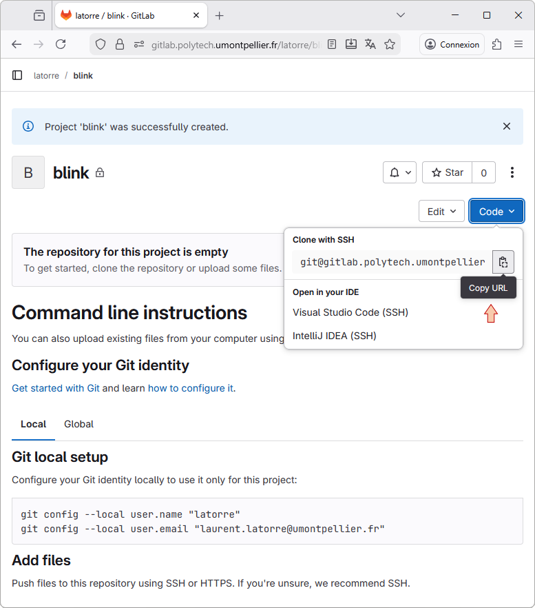
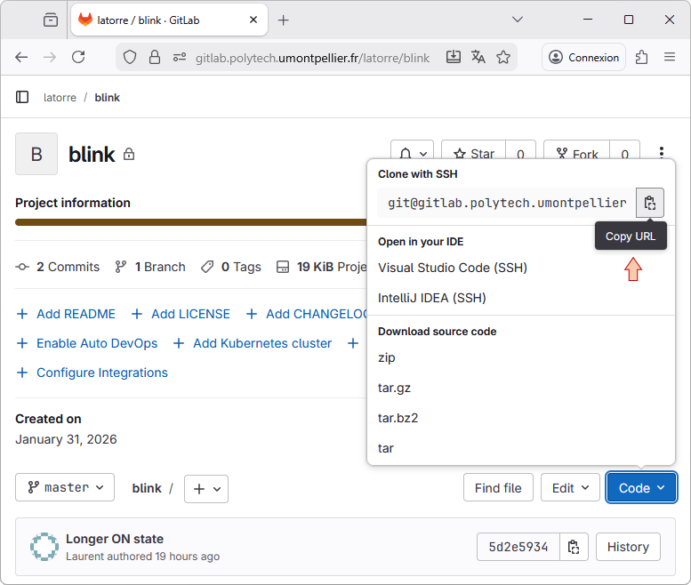
From GitlLab web interface, copy the project URL in the clipboard using the Copy SSH clone URL button:
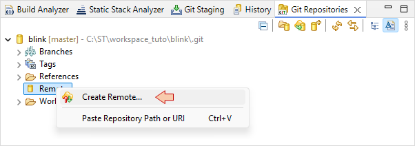
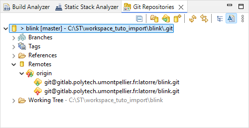
From STM32CubeIDE, using the blink project menu select Team → ![]() Show in Repositories View.
Show in Repositories View.
Then right-click on the Remote icon and select ![]() Create Remote.
Create Remote.
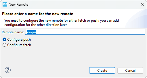
In the next dialog, just keep default Remote name origin and click Create.
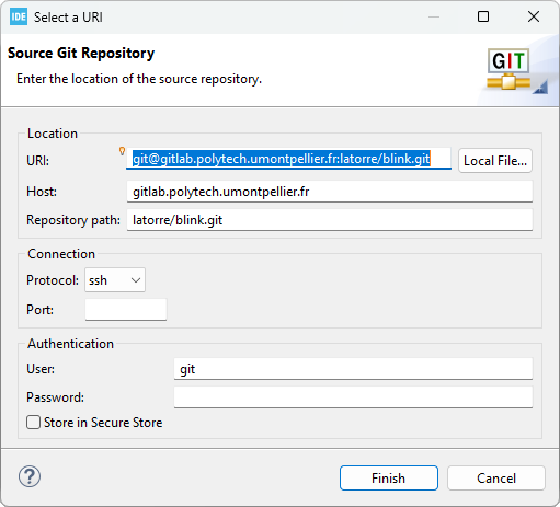
In the Configure Push dialog, click the Change... button.
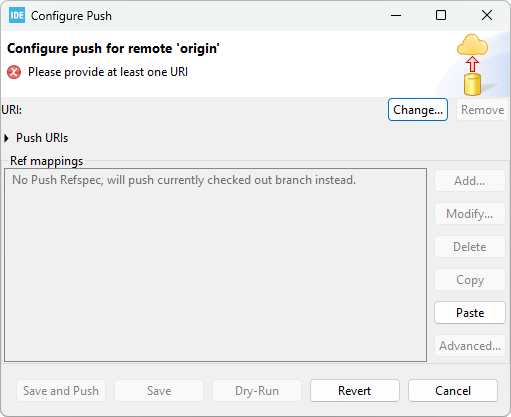
If you correctly copied the URL from GitLab, the Select a URI dialog is automatically filled. Review the fields but do not change anything and click the Finish button. If the fields are not filled, just try again.
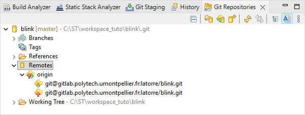
In the Configure Push dialog, click the Save button. The new remote repository should now appear in the Git Repositories view:
6.5. Perform the Push action
Everything is now in place for the first Push onto the GitLab server.
There are various ways to achieve this:
One way is simply using the contextual menu Team →
 Push Branch 'master'...
You can also open the
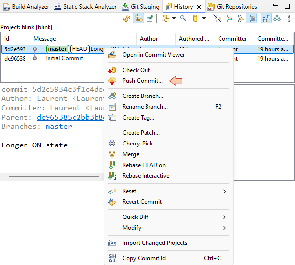
 History view, and then from the last commit contextual menu select Push Commit. Let's do that.
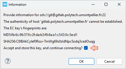
You'll get a first dialog that comes only the first time you're using new SSH keys. Click OK.
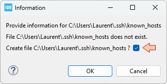
Same thing here.
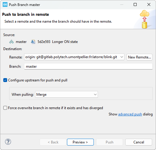
In the Push Branch master dialog, simply review the settings and click Preview > button.
And then Push button.
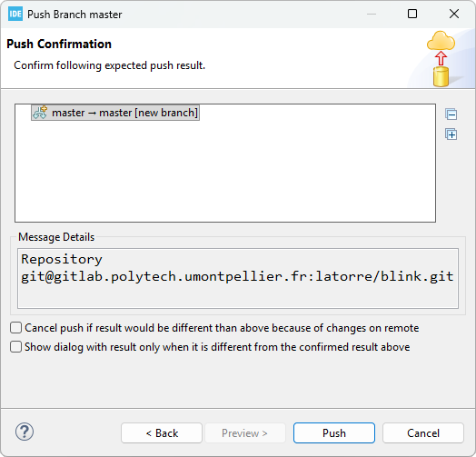
Is takes a short time to process the Push action. You can monitor the progress in the IDE bottom status bar:
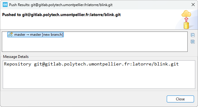
When complete, you should get a report. You can just close it, you're done!
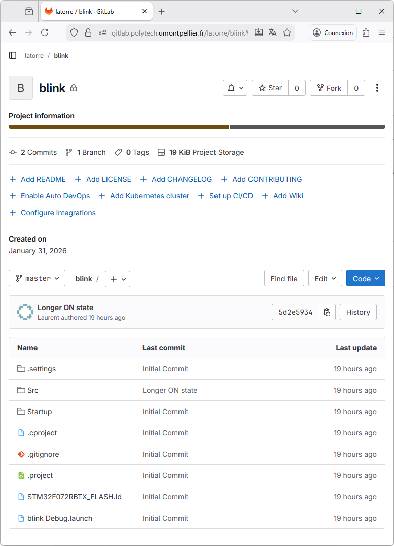
Refresh the project page on GitLab, you'll see that the last commit is now there. You can navigate within folder and files and even see the source code.
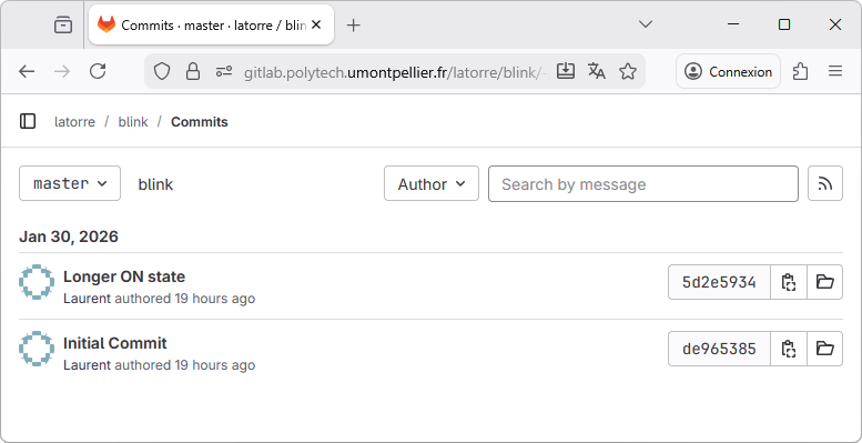
Actually, not only the last commit is there, but all the commit history. Click on the link:
The whole commit history is there:
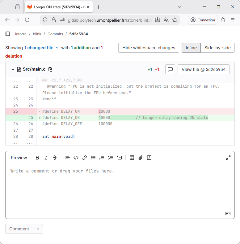
Select the Slower blinking link for detailed review. You'll see all the changes this commit holds, just like within STM32CubeIDE:
Before moving to the next section, let us summarize some important concepts:
The pushing action simply synchronizes the remote repository with your local repository.
Because a single commit only holds differences with respect to the previous commit, then when you push your last commit, Git needs all the history of changes since the first commit (i.e. the complete history).
For that reason, it is not possible to push a commit made on project_Y on top of an history built with project_X. Even if project_X and project_Y "look" the same. This happens if you move your project from a computer to another one, or if you change workspaces. You won't be allowed to continue pushing if the history is broken. The only way to migrate a project from a local repository to another one while keeping the link with the remote repository is to follow these steps:
1. Make sure before you move, that your source project is pushed and in sync with the remote repository
2. On the new computer (or new workspace) don't create a new destination project but import the one from the remote repository. Next section covers that topic.
3. From there, you may go on developing and committing and keep pushing onto the remote repository.
If for some reason at a given moment you can't push to the remote repository (no internet access, server temporarily unavailable, ...) you can keep going with local commits. Those are not lost. When you'll regain access to the remote server, then pushing the last commit will push everything between that commit and the last one that was already pushed onto the server.
7. Importing a project from GitLab
Because it is impossible for Eclipse to have two identical projects in the same workspace, you need to restart STM32CubeIDE with a fresh folder as workspace. That's only necessary for this section, and you may delete that folder when you're done.
From the main menu, select File → Switch Workspace → Other...
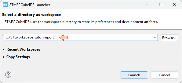
Choose a name for the new temporary workspace (e.g. 'workspace_tuto_import'), then click Launch. This will restart STM32CubeIDE with a fresh workspace.
Then, from the main menu, select File → ![]() Import...
Import...
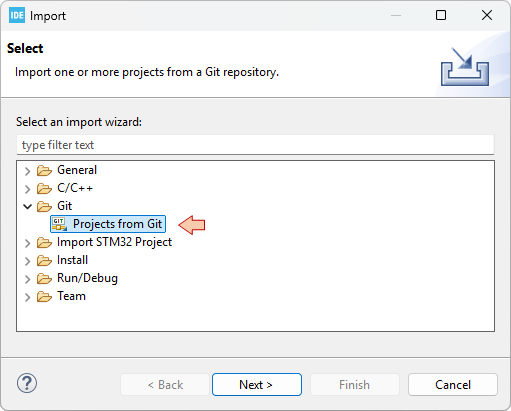
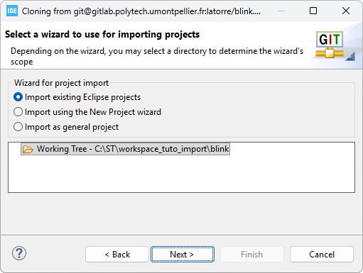
In the Import dialog, choose Git→ Projects from Git
Now, using GitLab, copy the project URL you want to import:
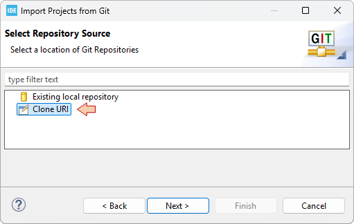
Then back to STM32CubeIDE, click Next and choose the Clone URI option:
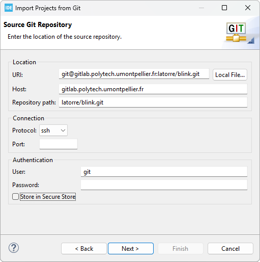
In the next dialog, paste (it usually comes automatically) the content of the clipboard and review the source information:
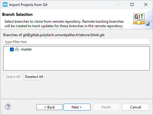
Click Next and EGit starts analyzing the remote repository information looking for branches to import. After a short time, you'll get this:
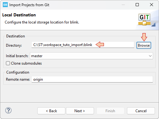
Click Next, then carefully select your temporary workspace folder as the Destination Directory:
In the next dialogs, just click Next, and then Finish.
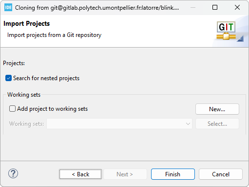
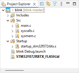
When done, the imported project appears in the Project Explorer:
It is not unusual to get some warnings here, because of missing paths, for instance, if project includes absolute paths from the original project.
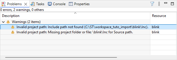
Just try and repair these warnings by reviewing the build settings. There's a warning here because the \Inc folder is missing. It is missing because as it is empty for now, and nothing was included into the commits. To remove this warning, you can just create an empty \Inc source folder, or delete the reference to this folder in the project properties:
Delete the ..\Inc include path in C/C++ Build→Settings→MCU/MPU GCC Compiler→Include paths
Delete the /blink/Inc path in C/C++ General→Paths and Symbols→Source Location
Just try to ![]() build the project. If you're lucky enough, it builds right-away first time with no errors. Even the debug configuration should be ready to go.
build the project. If you're lucky enough, it builds right-away first time with no errors. Even the debug configuration should be ready to go.
arm-none-eabi-size  blink.elf
arm-none-eabi-objdump -h -S blink.elf  > "blink.list"
   text	   data	    bss	    dec	    hex	filename
    648	      0	   1568	   2216	    8a8	blink.elf
Finished building: default.size.stdout
Finished building: blink.list
15:59:04 Build Finished. 0 errors, 0 warnings. (took 382ms)
As you may have noticed, the imported project is still associated with the Git repositories:
- A new local repository (in the project local folder)
- The same remote remote repository as the one you imported from
From there, you have two options depending on what you want to do
- If you want to keep on developing that project, then you can go on writing code, then committing then pushing onto the remote.
- If you imported that project as a base for another project, then you should disconnect it from the actual repositories using
Team → Disconnect.
IMPORTANT NOTICE FOR POLYTECH STUDENTS


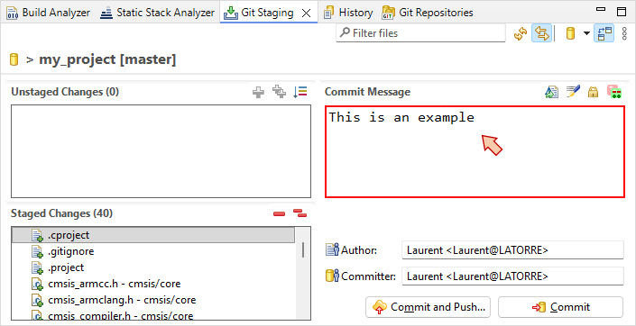
In the following tutorials, every time you pass by a red box as shown below, you have to commit current project state and then push into a dedicated repository on GitLab.
This special remote repository is provided and owned by teacher, but you'll have maintainer rights so you can basically do whatever you want. It is used to monitor your progression. This is part of the evaluation process, and since GitLab info extraction is automated, it is mandatory to use the indicated commit name as a commit message. To avoid typos, simply copy/paste that name (without " " please) into the Commit Message field of the Git Staging panel.
For example, if the box says so:
 | - - |
Commit the project using Commit name as Commit Message as shown here:
Be careful if your navigator translates the web site in a non-English language. Translated commit names will be discarded in the evaluation process... You've been warned.
For the very first commit (coming shortly), you'll have to configure the remote repository as explained in the above tutorial, using URI obtained from the remote repository. Then, you'll be able to execute first push. This will create the master branch onto GitLab repository.
You only need to configure the remote repository once. We'll use the same project all along the tutorials. For second commit and further, you may simply use the ![]() Commit & Push... button each time you pass by the red box.
Commit & Push... button each time you pass by the red box.
Last advice:
Keep all commits in the master branch (i.e. do not create other branches).
Check your commits both in STM32CubeIDE and in GitLab after the push action, especially the first ones, to make sure everything works as it should.
The tutorials program includes 44 commits. By the end of the training, your project history should display something similar to this:
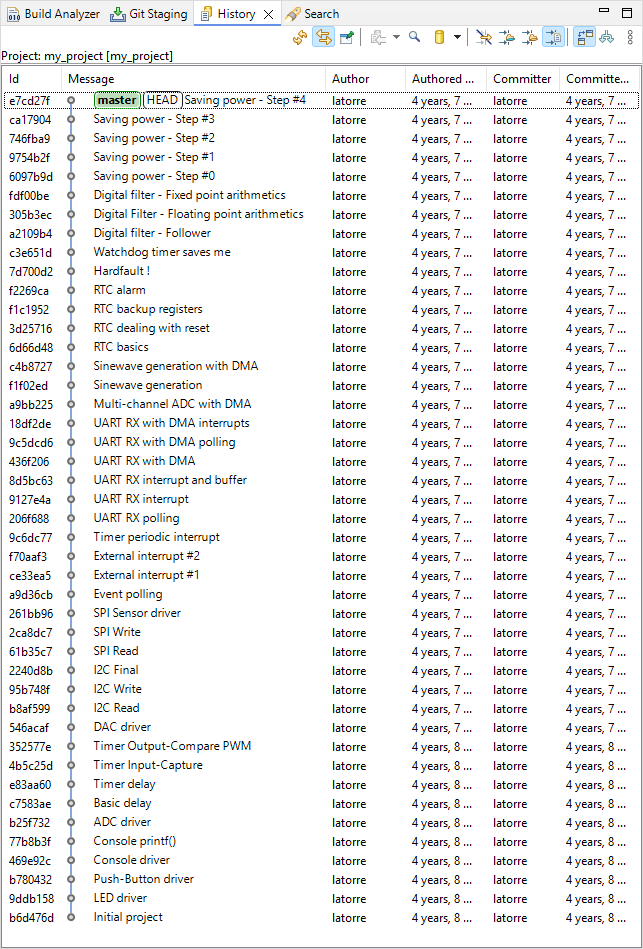
Take a breath, and let's go!
1.6. Importing & Cloning projects (2026)
1.6. Importing & Cloning projects (2026)
This tutorial proposes a method that can be used to duplicate projects. This is very useful for using existing projects or template projects as a base for a new application.
Although a simple copy/paste from the project explorer seems to work, I've found that many paths are not updated and still refer to the source project. I acknowledge that the method proposed below does not appear as the most convenient way to create duplicates, but I've been doing this for years and it seems to be robust enough to create perfectly independent clone projects.
You will need a separate text editor with good a Search/Replace tool. I suggest getting notepad++, but any other you like will do.
Cloning an existing project mostly consists in
- Duplicating the existing project folder
- Performing some manual edit in project configuration files to change its name
- Importing the new project into the workspace
Note that step 3 alone is very useful for importing projects that have been created elsewhere (another computer, another workspace, another developer, ...).
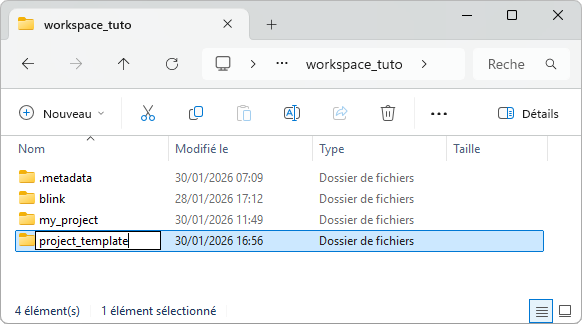
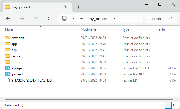
In this tutorial, we will duplicate the my_project project as a new project_template project.
1. Step #1 : Duplicate the source folder
Using your OS explorer, navigate into your workspace folder and copy/paste (create a duplicate) the my_project folder:
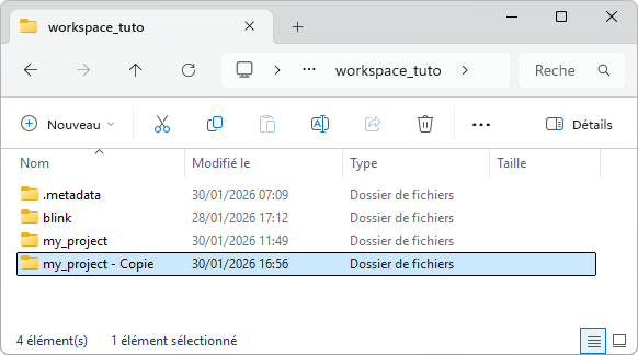
Rename that folder with the new project name project_template:
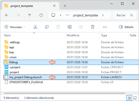
2. Step #2 : Clean & edit new project configuration files
Now open the project_template folder. Delete the Debug folder (these have been produced during build) and the debug/launch configuration file:
Then, open both ![]() and
and ![]() files into a text editor (preferably notepad++).
files into a text editor (preferably notepad++).
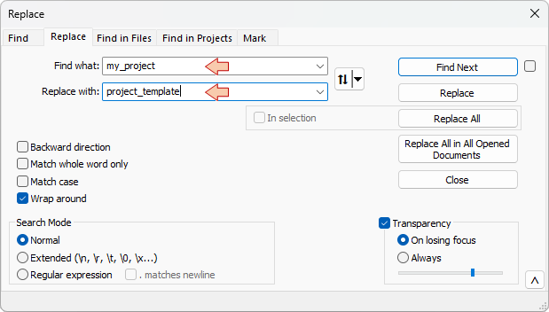
Search and Replace every occurrence of the old name my_project with the new name project_template.
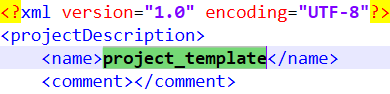
- In the .project file, there is usually only one occurrence within the <name> tag:
- In the .cproject file, there are several occurrences. In this example, 4 replacements were performed, but you may have more…
...
...

Save and close both .project and .cproject files. The new project is ready for import within STM32CubeIDE.
3. Step #3 : Import an existing project into STM32CubeIDE
Start STM32CubeIDE within the working workspace and close any opened project.
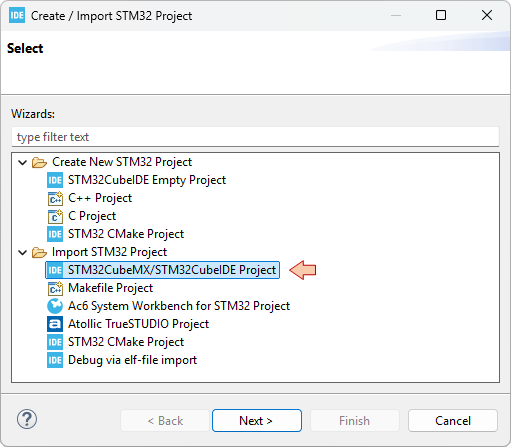
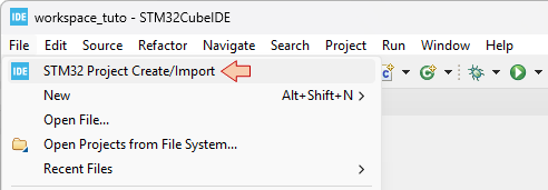
From the IDE main menu File →STM32 Project Create/Import
Choose STM32CubeMX/STM32CubeIDE Project from the Import STM32 Project folder and click Next
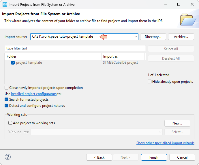
In the next dialog:
- Put the path (root directory) the to project you want to import in the Import source field.
- Tick the project you want to import
- Click Finish
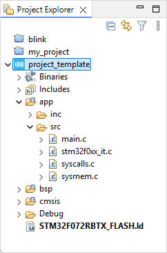
The new project project_template is now displayed in the Eclipse Project Explorer:
You should be able to build it ![]() without problem since all the build options you have set in the source project have been preserved during the cloning operation:
without problem since all the build options you have set in the source project have been preserved during the cloning operation:
arm-none-eabi-size  project_template.elf
arm-none-eabi-objdump -h -S project_template.elf  > "project_template.list"
   text	   data	    bss	    dec	    hex	filename
   1628	      4	   1564	   3196	    c7c	project_template.elf
Finished building: default.size.stdout
Finished building: project_template.list
17:42:11 Build Finished. 0 errors, 0 warnings. (took 438ms)
The ![]() Debug Configuration is empty as we did not keep the previous file settings. You'll need to do that by yourself. You did it before. Twice...
Debug Configuration is empty as we did not keep the previous file settings. You'll need to do that by yourself. You did it before. Twice...
1.5. Clock settings (2026)
1.5. Clock settings (2026)
1. Introduction
Clock settings are of primary importance when you start a new microcontroller project. The way you configure the clocking scheme has direct impact on peripheral programing, application performance and power consumption. This tutorial details the default configuration and provides a function to setup clock for maximum performance and stability. You absolutely need to understand and master the concepts introduced here.
2. STM32 Clock architecture
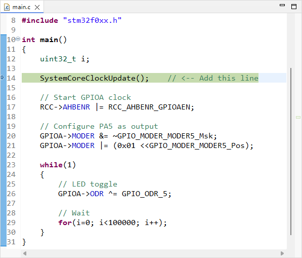
Open your my_project project and edit the main.c file. Add a call to the SystemCoreClockUpdate() at the beginning of the main() function. The SystemCoreClockUpdate() is implemented in system_stm32f0xx.c and is part of the CMSIS package. What it does is an update of the global variable SystemCoreClock using current hardware settings to calculate actual core clock frequency.
/*
 * main.c
 *
 *  Created on: 15 mai 2021
 *      Author: Laurent
 */
#include "stm32f0xx.h"
int main()
{
	uint32_t i;
	SystemCoreClockUpdate();	// <-- Add this line
	// Start GPIOA clock
	RCC->AHBENR |= RCC_AHBENR_GPIOAEN;
	// Configure PA5 as output
	GPIOA->MODER &= ~GPIO_MODER_MODER5_Msk;
	GPIOA->MODER |= (0x01 <<GPIO_MODER_MODER5_Pos);
	while(1)
	{
		// LED toggle
		GPIOA->ODR ^= GPIO_ODR_5;
		// Wait
		for(i=0; i<100000; i++);
	}
}
Save ![]() , build
, build ![]() , and fire a debug session
, and fire a debug session ![]() .
.
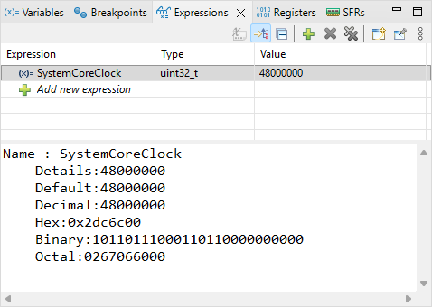
In the Expressions view, add the SystemCoreClock global variable, then step over ![]() the SystemCoreClockUpdate() function and watch the value of SystemCoreClock:
the SystemCoreClockUpdate() function and watch the value of SystemCoreClock:
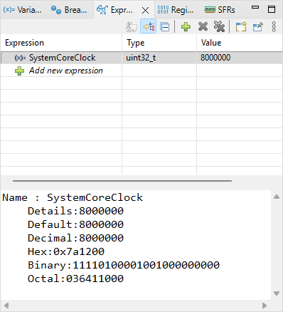
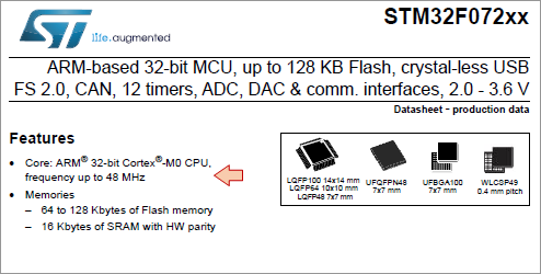
SystemCoreClock = 8000000, so actual CPU frequency is 8MHz. The device datasheet reveals that SMT32F072 runs fine up to 48MHz, so we have room for a 6× faster CPU. How can we do that?
- By understanding the clock scheme of the device.
- By writing a function to configure the clock scheme for 48MHz operation.
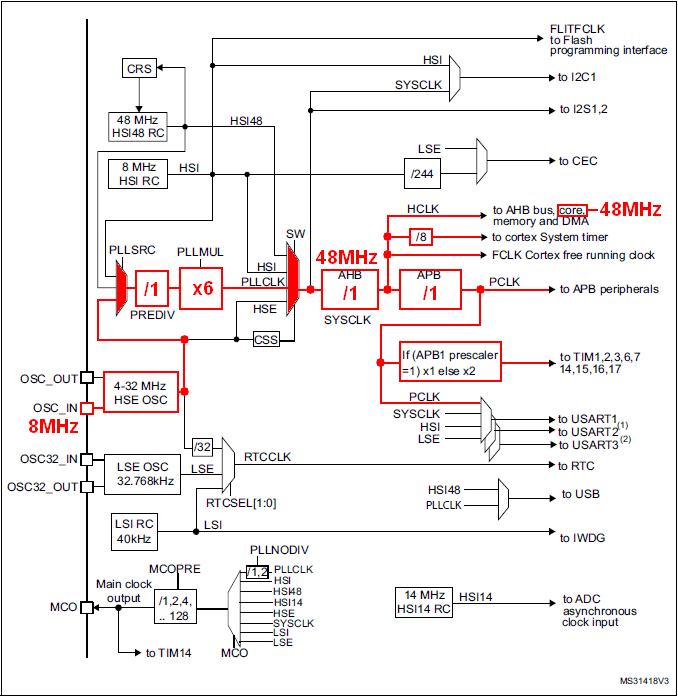
3. Understanding the Clock scheme
The RCC (Reset and Clock Controller) chapter of the Reference Manual provides a block schematics of the clock distribution architecture.
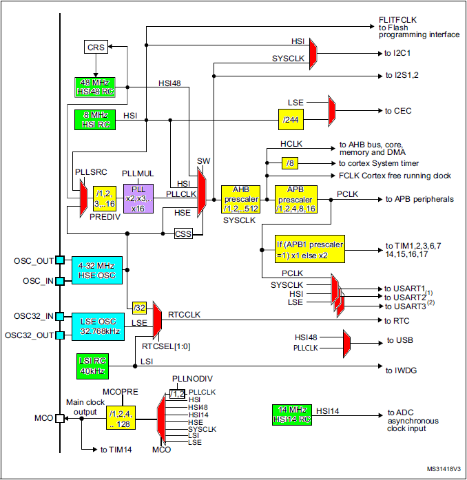
The above picture represents the full hardware architecture of the MCU internal clock system. We find:
- Green: Internal clock sources (RC oscillators) → Available at no additional costs, but neither very precise, nor very stable across the temperature range.
- High Speed : HSI RC, HSI48 RC, HSI14 RC → default RC-based oscillator for CPU and peripherals.
- Low Speed : LSI RC → always used with the watchdog timer.
- Blue: Inputs for external clock sources (Crystal oscillators) → Required if clock precision and stability are required.
- High Speed : HSE → the de facto input for high-speed crystal-based oscillator for CPU and peripherals fast and stable clocking.
- Low Speed : LSE → mostly used with RTC.
- Red: Multiplexers for clock routing (one input among n is connected to the output)
- Yellow: Frequency dividers (prescalers)
- Purple: Frequency multiplier (PLL)
By fine tuning all these boxes, you can achieve a large amount of different clock configurations. Why is it that complex? Because clock frequency and power consumption are tightly linked. Basically, you want the lowest possible frequency, as long as you get the performance your application requires.
Hence, in power-aware embedded systems, basic approaches are:
- We only provide a clock signal to the hardware peripherals that the application needs
- We lower the clock frequency as much as we can to meet performance requirements
- We use Low-Power modes (sleep, stop, standby) whenever we can
4. Understanding the default configuration
In our project, so far, the clock configuration is done at startup via a call to the SystemInit() function. Note that SystemInit() is called from the startup script prior calling main(). Therefore a clock configuration can be performed before your program actually starts executing.
Yet, as you can see, the SystemInit() function (in system_stm32f0xx.c) has been left empty, and that's up to you to customize it.
/**
  * @brief  Setup the microcontroller system
  * @param  None
  * @retval None
  */
void SystemInit(void)
{
  /* NOTE :SystemInit(): This function is called at startup just after reset and
                         before branch to main program. This call is made inside
                         the "startup_stm32f0xx.s" file.
                         User can setups the default system clock (System clock source, PLL Multiplier
                         and Divider factors, AHB/APBx prescalers and Flash settings).
   */
}
As a result, the 8MHz we observe from the SystemCoreClock global variable comes from the default hardware clock configuration at startup (reset state), which in turn is a consequence of the registers that configure the above clock scheme reset states . These registers are part of the RCC (Reset & Clock Control) peripheral. Refer to the the Reference Manual to fully understand the table below.
| RESET STATE | BITS | EFFECT | |
| RCC_CR | 0x0000 XX83 |
|
|
| RCC_CFGR | 0x0000 0000 |
|
|
The corresponding path is highlighted below. The so-called core is the CPU. It receives a 8MHz clock.
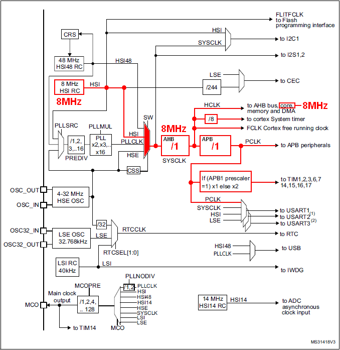
Note that configuration at startup only relies on internal (and therefore available) resources. Doing so guaranties that software always start executing at power on, regardless the availability of external clock sources.
5. Writing a new clock configuration function
Assume we want to push the processor to its 48MHz limit, and then use HSE as the clock source for more stability.
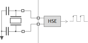
The HSE hardware supports two different configurations (modes):
The Oscillator Mode: In this mode, HSE is connected to a crystal/capacitor network. HSE drives this network (unstable closed-loop amplifier) in order to produce oscillations
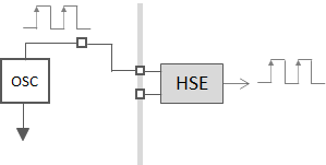
The Bypass Mode: In this mode, HSE receives a clock from an external source on the board. HSE does nothing but letting that clock passing through it.
Looking at the board schematics, we see that the 2 options have been anticipated on the PCB. We can either use:
the X3/C33/C34 network with HSE in Oscillator Mode
or the ST-Link MCO (Master Clock Output) clock source with HSE in Bypass Mode
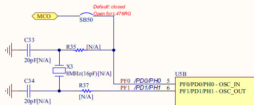
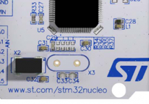
But looking closer on the board itself, you will see that X3/C33/C34 and R35, R37 are not actually fitted. Footprints are there, but if you want it, you have to buy the parts and then find yourself a soldering iron...
So we're left with the second option, i.e. using the ST-Link MCO as our HSE source, with HSE in Bypass Mode. The user manual also states that ST-Link MCO is a fixed 8MHz frequency clock.
As we want to achieve a 48MHz CPU clock frequency from the 8MHz external clock source, we need something that multiplies frequencies. This is the purpose of the PLL (Phase Locked Loop) circuit. Using a ×6 multiplication factor within the PLL, we can obtain the targeted 48MHz for the CPU and peripherals.
In summary, the configuration we want is:
Practically, this will be achieved by writing a function that does (in this order):
- Enable HSE in Bypass Mode and make sure it is READY (should already be)
- Choose HSE as the selected input on the PLL Source Mux
- Set the PLL prescaler PREDiv to /1 and the multiplication factor PLLMul to ×6
- Start the PLL and make sure it is READY
- Make sure AHB Prescaler and APB Prescaler are set such that system (CPU & peripherals) will cope with the new frequency
- Switch the System Clock Mux intput, from HSI to PLLCLK → At this moment only will the system clock get boosted.
6. Let's boost the system
Using the my_project project, open main.c in the editor. Copy/paste the following function below the main() function. Comments should help you understand what the code does but basically, it just sets the RCC peripheral as above discussed.
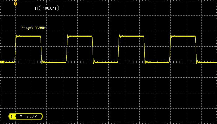
In addition, it sets PA8 pin as MCO (Master Clock Output). This is not mandatory. It only provides a convenient way to measure the internal clock frequency with an oscilloscope. Yet, in order to cope with oscilloscopes bandwidth, the 48MHz is divided by /16 (within the MCOPRE prescaler) so that MCO pin actually exhibits a 3MHz square signal.
/*
 * 	Clock configuration for the Nucleo STM32F072RB board
 * 	HSE input Bypass Mode         -> 8MHz
 * 	SYSCLK, AHB, APB1             -> 48MHz
 *  PA8 as MCO with /16 prescaler -> 3MHz
 *
 *  Laurent Latorre - 05/08/2017
 */

static void SystemClock_Config()
{
	uint32_t	HSE_Status;
	uint32_t	PLL_Status;
	uint32_t	SW_Status;
	uint32_t	timeout = 0;
	timeout = 1000000;

	// Start HSE in Bypass Mode
	RCC->CR |= RCC_CR_HSEBYP;
	RCC->CR |= RCC_CR_HSEON;

	// Wait until HSE is ready
	do
	{
		HSE_Status = RCC->CR & RCC_CR_HSERDY_Msk;
		timeout--;
	} while ((HSE_Status == 0) && (timeout > 0));

	// Select HSE as PLL input source
	RCC->CFGR &= ~RCC_CFGR_PLLSRC_Msk;
	RCC->CFGR |= (0x02 <<RCC_CFGR_PLLSRC_Pos);

	// Set PLL PREDIV to /1
	RCC->CFGR2 = 0x00000000;

	// Set PLL MUL to x6
	RCC->CFGR &= ~RCC_CFGR_PLLMUL_Msk;
	RCC->CFGR |= (0x04 <<RCC_CFGR_PLLMUL_Pos);

	// Enable the main PLL
	RCC-> CR |= RCC_CR_PLLON;

	// Wait until PLL is ready
	do
	{
		PLL_Status = RCC->CR & RCC_CR_PLLRDY_Msk;
		timeout--;
	} while ((PLL_Status == 0) && (timeout > 0));

    // Set AHB prescaler to /1
	RCC->CFGR &= ~RCC_CFGR_HPRE_Msk;
	RCC->CFGR |= RCC_CFGR_HPRE_DIV1;

	//Set APB1 prescaler to /1
	RCC->CFGR &= ~RCC_CFGR_PPRE_Msk;
	RCC->CFGR |= RCC_CFGR_PPRE_DIV1;

	// Enable FLASH Prefetch Buffer and set Flash Latency
	FLASH->ACR = FLASH_ACR_PRFTBE | FLASH_ACR_LATENCY;

	/* --- Until this point, MCU was still clocked by HSI at 8MHz ---*/
	/* --- Switching to PLL at 48MHz Now!  Fasten your seat belt! ---*/

	// Select the main PLL as system clock source
	RCC->CFGR &= ~RCC_CFGR_SW;
	RCC->CFGR |= RCC_CFGR_SW_PLL;

	// Wait until PLL becomes main switch input
	do
	{
		SW_Status = (RCC->CFGR & RCC_CFGR_SWS_Msk);
		timeout--;
	} while ((SW_Status != RCC_CFGR_SWS_PLL) && (timeout > 0));

	/* --- Here we go! ---*/

	/*--- Use PA8 as MCO output at 48/16 = 3MHz ---*/

	// Set MCO source as SYSCLK (48MHz)
	RCC->CFGR &= ~RCC_CFGR_MCO_Msk;
	RCC->CFGR |=  RCC_CFGR_MCOSEL_SYSCLK;

	// Set MCO prescaler to /16 -> 3MHz
	RCC->CFGR &= ~RCC_CFGR_MCOPRE_Msk;
	RCC->CFGR |=  RCC_CFGR_MCOPRE_DIV16;

	// Enable GPIOA clock
	RCC->AHBENR |= RCC_AHBENR_GPIOAEN;

	// Configure PA8 as Alternate function
	GPIOA->MODER &= ~GPIO_MODER_MODER8_Msk;
	GPIOA->MODER |= (0x02 <<GPIO_MODER_MODER8_Pos);

	// Set to AF0 (MCO output)
	GPIOA->AFR[1] &= ~(0x0000000F);
	GPIOA->AFR[1] |=  (0x00000000);

	// Update SystemCoreClock global variable
	SystemCoreClockUpdate();
}
Then declare the SystemClock_Config() function prototype at the beginning of main.c and insert a call to this function at the beginning of main() :
static void SystemClock_Config (void);    // <-- Function prototype

int main()
{
	uint32_t i;
	SystemClock_Config();                // <-- Call to the clock configuration function
	// Start GPIOA clock
	RCC->AHBENR |= RCC_AHBENR_GPIOAEN;
	// Configure PA5 as output
	GPIOA->MODER &= ~GPIO_MODER_MODER5_Msk;
	GPIOA->MODER |= (0x01 <<GPIO_MODER_MODER5_Pos);
	while(1)
	{
		// LED toggle
		GPIOA->ODR ^= GPIO_ODR_5;
		// Wait
		for(i=0; i<100000; i++);
	}
}
Save ![]() , build
, build ![]() , and fire a debug session
, and fire a debug session ![]() .
.
At the beginning of main(), the SystemCoreClock variable should still be 8000000 (8MHz). Then step over ![]() the SystemClock_Config() function and watch the Expression view. The SystemCoreClock variable should be now 48000000 (48MHz). Well done!
the SystemClock_Config() function and watch the Expression view. The SystemCoreClock variable should be now 48000000 (48MHz). Well done!
Run ![]() the program and watch the LED... blinking has become pretty nervous, hasn't it?
the program and watch the LED... blinking has become pretty nervous, hasn't it?
Probe PA8 pin with an oscilloscope. You should see a 3MHz clock (as a result of 48MHz /16):
Then suspend the execution ![]() and keep probing PA8. What do you see? Can you explain?
and keep probing PA8. What do you see? Can you explain?
You can terminate ![]() the debug session and switch back to the C/C++ perspective.
the debug session and switch back to the C/C++ perspective.
7. Summary
In this tutorial, we introduced the clock setup in the STM32. User settings define clock frequencies for the CPU and for the various peripherals (buses). This is a matter of primary importance:
- You can't configure peripherals, especially timers and communication peripherals if you don't know what their clock frequency is.
- The clock frequency can be changed on-the-fly, depending on the application requirements or the available power at a given moment.
- As you can see, there are several clock domains in the MCU. Fine tuning each domain to the minimum required frequency, at every moment of the application life, is a key for power savings.
At this moment, we tuned clock for maximum operating frequency. Therefore, we considered the performance before the power consumption. All along the subsequent tutorials, we will assume that performance is the priority and keep using that clock configuration, but keep in mind that it is not power friendly.
A good approach would be to start a development at maximum speed, then measure what is really needed for the application to perform flawlessly, and finally to reduce the frequency to what is just needed.
1.4. Project template (2026)
1.4. Project template (2026)
In this tutorial, let us create from scratch a minimal project that include everything we actually need to start programming STM32 devices. It is based on the initial blink demo project, but we will bring some additional headers and functions in, that makes the coding a bit more explicit.
With minor adaptations, you may consider this tutorial as a reference for starting new projects with any STM32 devices.
1. Create a New Project
Using the Project Explorer, close any projects that have been left open.
The first steps are the same as for the 1.2. Hello World tutorial. You can repeat the operations of section #1 "Creating a new project" without any changes, except the name you provide for the project. Let's replace "blink" by "my_project".
When done, give a try building ![]() the project to make sure everything is in place so far.
the project to make sure everything is in place so far.
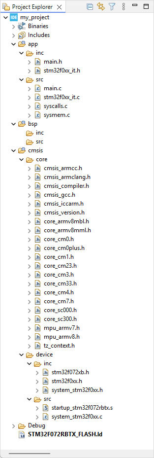
You should end up with this project structure:
2. Edit the project structure (folders)
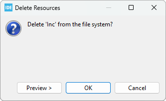
Using the contextual (right-click) menu, delete the /Inc folder.
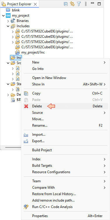
And confirm you want to remove it from the filesystem (hard drive):
Do not worry for now if the include path ![]() generates a warning. Obviously, that path doesn't exist anymore. We'll fix that later.
generates a warning. Obviously, that path doesn't exist anymore. We'll fix that later.
Then, still using the contextual menu (right-click) within the Project Explorer and selecting:
- New →

- New →

create the following folder structure:
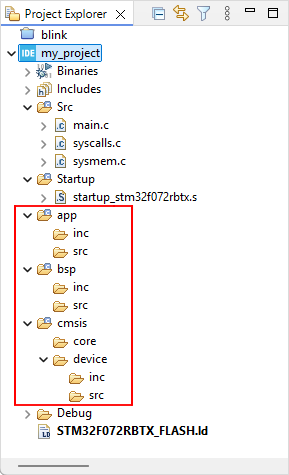 |
|
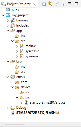
Now, within the project explorer:
Drag-n-drop (move) the 3 source files (main.c, syscalls.c, sysmem.c) from the /Src folder, to the /app/src folder
Delete the /Src folder
Drag-n-drop (move) the startup_stm32f072rbtx.s file from the /Startup folder, to the /cmsis/device/src folder
Delete the /Startup folder
The resulting project files and folder structure now is:
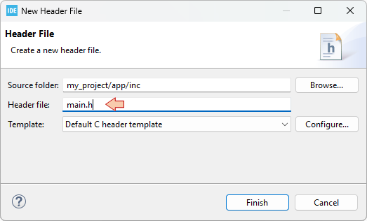
Finally, using again the contextual menu with New→![]() , add a new header main.h to the /app/inc folder. Select the Default C header template and click Finish.
, add a new header main.h to the /app/inc folder. Select the Default C header template and click Finish.
Note that this folder structure is only a suggestion. If you know what you are doing, you can organize files the way you want and even put everything below root folder, although not recommended…
As your project grows, the number of source files can become really big. You need a clean file structure that you know and understand well to navigate comfortably between sources. The sooner you get familiar with your choice of folder structure, the better. Even for small projects.
3. Get the CMSIS files
A STM32 microcontroller, just like many others MCUs from several silicon vendors, is designed around an ARM Cortex-M core processor. All ARM-based microcontrollers come with a set of source files as defined by ARM under the Cortex Microcontroller Software Interface Standard (CMSIS) specification.

https://developer.arm.com/tools-and-software/embedded/cmsis
Practically, it is only few files you have to include in your project structure. These files are illustrated below :
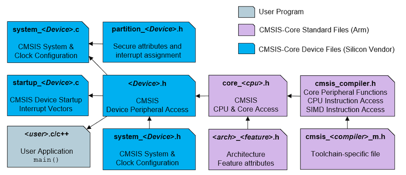
Note that we already have the startup file.
In order to get up-to-date CMSIS source files, a good option is to download the latest release of STM32 Cube libraries for the targeted device familly (STM32F0 here). It comes as a pretty big package including HAL libraries, but do not worry, we will only pick-up few files from this package.
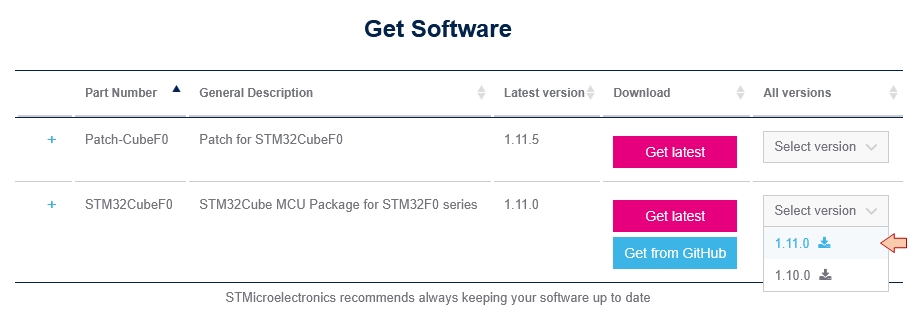
You can get the STM32F0 Cube library from ST website : https://www.st.com/en/embedded-software/stm32cubef0.html (Version 1.11.0 at time of writing).
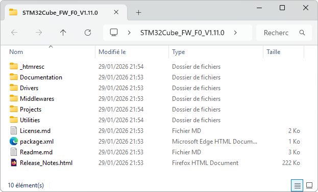
Unzip the downloaded archive and open the folder:
In another window, open your project folder (located in your workspace folder):
Then copy/paste the following files, from the Cube library, into your project folders:
| File(s) | Source folder | Destination folder |
| *.h | \Drivers\CMSIS\Include\ | \cmsis\core\ |
| system_stm32f0xx.h | \Drivers\CMSIS\Device\ST\STM32F0xx\Include | \cmsis\device\inc |
| system_stm32f0xx.c | \Drivers\CMSIS\Device\ST\STM32F0xx\ Source\Templates | \cmsis\device\src |
| stm32f0xx.h, stm32f072xb.h | \Drivers\CMSIS\Device\ST\STM32F0xx\Include | \cmsis\device\inc |
| stm32f0xx_it.h | \Projects\STM32F072RB-Nucleo\Templates\Inc | \app\inc |
| stm32f0xx_it.c | \Projects\STM32F072RB-Nucleo\Templates\Src | \app\src |
If you are working with a device other than the STM32F072RB, just adapt the previous table to your needs… All ST's Cube libraries share the same file structure and naming convention.
Back into Eclipse, Refresh the Project Explorer (press F5). Your project structure now should be:
Some more explanations about files we've just added to the project:
The core headers are required to access dedicated CPU functionalities, which are not part of ST hardware. For instance, we use core CPU functions to configure the system timer (Systick), the Nested Vector Interrupt Controller (NVIC), and Low-Power modes.
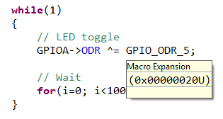
STM32F0 headers (stm32f0xx.h, stm32f072xb.h) contain definitions (aliases) for all STM32 peripheral registers and their content. It is not a library, it is basically nothing more than a huge (≈10.000) list of #define. It allows calling a register and associated bit by names instead of addresses. For example, the code below we used to toggle the LED state (pin PA5) in previous labs:
*(int *)0x48000014 ^= 0x00000020U;can now be written:
GPIOA->ODR ^= GPIO_ODR_5;which is exactly same code, as there are just a #define behind GPIOA, ODR, GPIO_ODR_5 labels. Still, it makes code writing and reading way more comfortable. When hovering the mouse over a defined symbol, you get a bubble info that provides the definition:
These headers also include data types based on <stdint.h> that we will use instead of standard C types for integer numbers:
| C types | Embedded types |
| char | int8_t |
| unsigned char | uint8_t |
| short | int16_t |
| unsigned short | uint16_t |
| int | int32_t |
| unsigned int | uint32_t |
system_stm32.c and system_stm32.h provide few functions and macros you may want to use. In particular, the default clock settings are defined here and called from the startup routine.
stm32f0xx_it.c and stm32f0xx_it.h are there to implement interrupt handlers. This topic is addressed later.
4. Setting project build properties
At this moment, if you try the build ![]() button, it won't work. We need to configure the build first.
button, it won't work. We need to configure the build first.
Right-click on the project folder and select ![]() → Properties
→ Properties
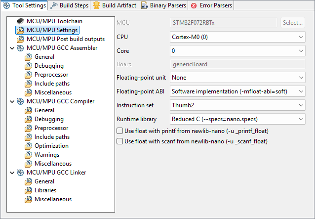
Select the C/C++ Build→Settings
In the MCU/MPU Settings section, review the MCU fields for your target device (just as we did in the "Hello World" tutorial):
In the MCU/MPU GCC Linker, General section, review the path to your Linker Script (just as we did in the "Hello World" tutorial):
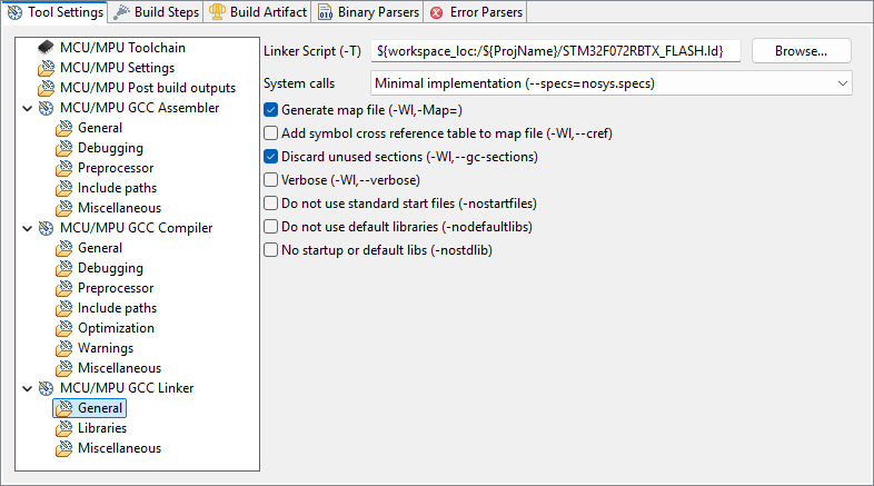
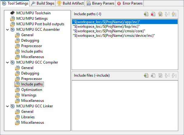
In the MCU/MPU GCC Compiler, Include paths section, you must provide paths to all the header files (.h) in your project. In our example, we have (or will have) headers in:
- /app/inc
- /bsp/inc
- /cmsis/core
- /cmsis/device/inc
First, use the Delete ![]() button to remove the obsolete path to ..\Inc folder
button to remove the obsolete path to ..\Inc folder
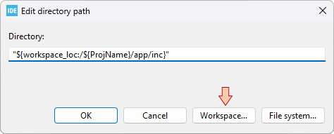
Then use the Add ![]() button and then browse the Workspace to select folders. Doing so avoids mistakes and write portable paths.
button and then browse the Workspace to select folders. Doing so avoids mistakes and write portable paths.
Make sure all 4 paths are defined as follows:
When you're done, click the Apply & Close button of the Properties dialog.
Try the build ![]() button and watch the console. You should get several errors. Scroll up to the first one:
button and watch the console. You should get several errors. Scroll up to the first one:
C:/STM/workspace_tuto/blink3/cmsis/device/inc/stm32f0xx.h:159:3: error: #error "Please select first the target STM32F0xx device used in your application (in stm32f0xx.h file)"
  159 |  #error "Please select first the target STM32F0xx device used in your application (in stm32f0xx.h file)"
      |   ^~~~~
This error is reported from within the stm32f0xx.h header:
#else
 #error "Please select first the target STM32F0xx device used in your application (in stm32f0xx.h file)"
#endif
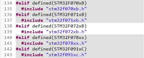
You'll notice that device headers #include above that line are actually all grayed-out, meaning that no header is in fact included. The reason is that you must select which particular device you want to target in this project.
There are 2 ways to to that:
By editing the stm32f0xx.h header. You can either:
Add this
#define STM32F072xBAt the beginning of the header
Or simply un-comment the following line:
/* #define STM32F072xB */ /*!< STM32F072x8, STM32F072xB Devices (STM32F072xx microcontrollers where the Flash memory ranges between 64 and 128 Kbytes) */
By adding a preprocessor symbol in the build configuration. I definitely recommend this method because it leaves ST headers clean from any modification so that you can reuse those in another project without troubles.
Go back to project properties, under C/C++ Build→Settings, and open the MCU/MPU GCC Compiler, Preprocessor section. In the Define symbols area, start by removing ![]() all of the previously defined symbols.
all of the previously defined symbols.
Then click the Add ![]() button and edit the symbol you want to add:
button and edit the symbol you want to add:
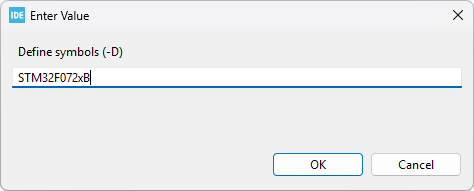
Make sure the symbol has been added, and then Apply & Close the Properties dialog.
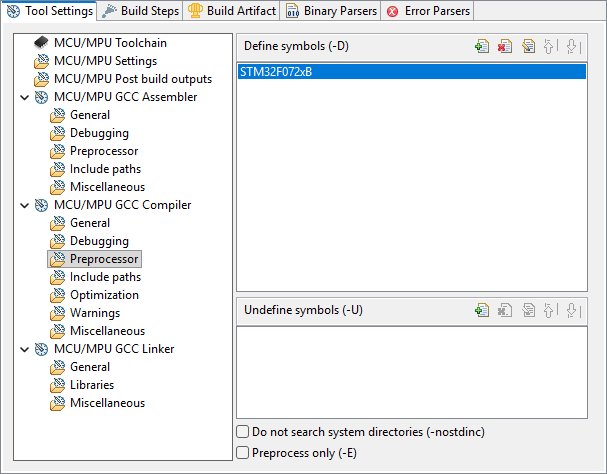
You can notice immediate effect in the stm32f0xx.h header. The stm32f072xb.h header is no more grayed-out!
We're almost done... One last thing to do is to edit the stm32f0xx_it.c file. Comment out the call to HAL_IncTick() int the SysTick_Handler() function. We're not using HAL libraries.
/**
  * @brief  This function handles SysTick Handler.
  * @param  None
  * @retval None
  */
void SysTick_Handler(void)
{
  // HAL_IncTick();           // <- Comment this line
}
Well done. Save all ![]() .
.
5. New blinking demo
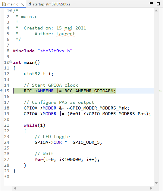
Delete all the content of the main.c file (CRTL+A, Suppr) and replace it with this one:
/*
 * main.c
 *
 *  Created on: 15 mai 2021
 *      Author: Laurent
 */

#include "stm32f0xx.h"

int main()
{
	uint32_t i;

	// Start GPIOA clock
	RCC->AHBENR |= RCC_AHBENR_GPIOAEN;

	// Configure PA5 as output
	GPIOA->MODER &= ~GPIO_MODER_MODER5_Msk;
	GPIOA->MODER |= (0x01 <<GPIO_MODER_MODER5_Pos);

	while(1)
	{
		// LED toggle
		GPIOA->ODR ^= GPIO_ODR_5;

		// Wait
		for(i=0; i<100000; i++);
	}
}
6. Build and debug
Hit the build ![]() button and perform the usual checks:
button and perform the usual checks:
watch the Console. The build should pass without any warning or error:
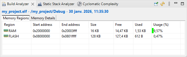
arm-none-eabi-size  my_project.elf
arm-none-eabi-objdump -h -S my_project.elf  > "my_project.list"
   text	   data	    bss	    dec	    hex	filename
    612	      0	   1568	   2180	    884	my_project.elf
Finished building: default.size.stdout
Finished building: my_project.list
11:35:31 Build Finished. 0 errors, 0 warnings. (took 3s.292ms)
Have a look on the Build Analyzer and check memory levels:
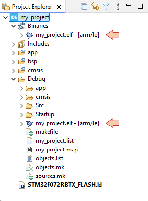
Make sure binaries and debug data has been updated in the Project Explorer:
Then, move on to the Debug Configuration ![]() . You did already, just setup the debug configuration:
. You did already, just setup the debug configuration:
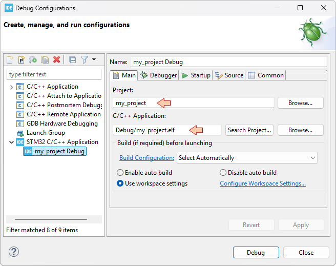
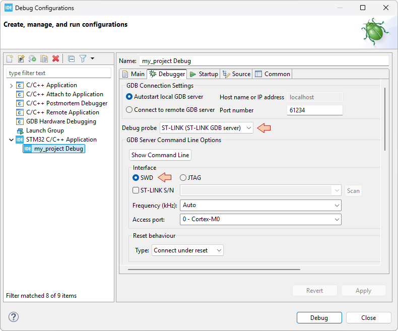
And then make sure that the debugger session launches with no problems:
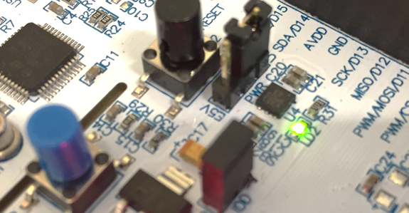
Finally try running the program with the usual debugger commands (![]() ,
, ![]() ,
, ![]() ), make sure the LED is still blinking...
), make sure the LED is still blinking...
... then exit the debug session ![]() . Well done!
. Well done!
7. Summary
In this tutorial, we've seen an approach to start new STM32 projects from scratch, using STM32CubeIDE. Such approach should be portable across other IDEs if you like.
The so-prepared project features:
- Full CMSIS layer including:
- Startup code
- System initialization functions
- Device headers enabling the use of embedded types and peripheral aliases (instead of magic numbers)
- The LinkerScript
1.3. Running the debugger (2026)
1.3. Running the debugger (2026)
1. Prepare the project
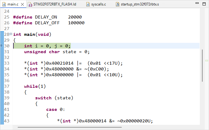
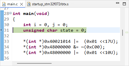
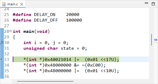
Open the blink project from previous tutorial and change the content of main() function to this:
#define DELAY_ON	20000
#define DELAY_OFF	100000

int main(void)
{
    int i = 0, j = 0;
    unsigned char state = 0;

	*(int *)0x40021014 |=  (0x01 <<17U);
	*(int *)0x48000000 &= ~(0xC00);
	*(int *)0x48000000 |=  (0x01 <<10U);

	while(1)
	{
		switch (state)
		{
			case 0:
			{
				*(int *)0x48000014 &= ~0x00000020U;
				i++;
				if (i>DELAY_OFF)
				{
					i = 0;
					j++;
					state = 1;
				}
				break;
			}
			case 1:
			{
				*(int *)0x48000014 |= 0x00000020U;
				i++;
				if (i>DELAY_ON)
				{
					i = 0;
					state = 0;
				}
				break;
			}
		}
	}
}
Save all ![]() and build
and build ![]() the project. There must be no error or warning:
the project. There must be no error or warning:
arm-none-eabi-size  blink.elf
arm-none-eabi-objdump -h -S blink.elf  > "blink.list"
   text	   data	    bss	    dec	    hex	filename
    648	      0	   1568	   2216	    8a8	blink.elf
Finished building: default.size.stdout

Finished building: blink.list

18:42:04 Build Finished. 0 errors, 0 warnings. (took 391ms)
2. A word on the build report
Before we dive into the debug, let us stop by the information we already have from the build process.
The build report provides data regarding the memory usage of the project:
   text	   data	    bss	    dec	    hex	filename
    648	      0	   1568	   2216	    8a8	blink.elf
These numbers relate to two different physical memories:
The FLASH memory (where the program is stored, non-volatile)
The RAM memory (where the variables live during code execution, volatile)
Basically:
text reports the size of the program to be stored into the FLASH memory (in bytes).
data reports the amount (in bytes) of "non-zero-initialized global or static variables".
When we declare, as global (or static):int id=5;4 bytes are allocated into the RAM to hold the id variable.
Another 4 bytes are allocated into the FLASH to store the number 5.
The startup code is in charge of transferring the number 5 into the variable id before you enter the main() function.
bss reports the amount (in bytes) of "zero-initialized or uninitialized global or static variables.
When we declare as global (or static):int id1; int id2=0;- 4 bytes are allocated into RAM for each id1 and id2 variables.
The startup code initialize id1 and id2 to zero. There is no need to store anything else.
- 4 bytes are allocated into RAM for each id1 and id2 variables.
- dec and hex are the sum (text + data + bss) in decimal and hexadecimal representations, respectively.
The drawing below illustrates the numbers provided by the build report:
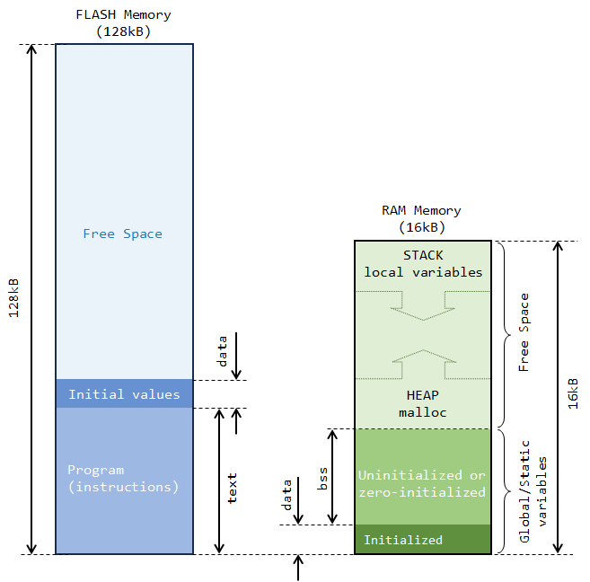
In summary, regarding RAM usage, the build only reports what is statically allocated. It is important to note that, most of the time, a large part of the RAM that a project actually needs comes from variables that are local to the (many) functions the program calls (including main()). Those variables are nowhere in the build report, for the reason that it is impossible to predict what will be actually needed before... well execution. In our case, i, j, and state variables are not part of the build report.
Then a question arises...
Why is there about 1.5kB of bss reported here? We have nothing declared as static or global!
Let us first remember how a program works with memory. On one hand, variables local to a function are dynamically created when the function is called, and destroyed when the function returns. The RAM region where this process occurs is called the Stack. On the other hand, dynamic allocation within the program (malloc) takes place in another region of RAM called the Heap. Heap and Stack grow and shrink at the both ends of RAM free space. The free space is simply all the RAM that remains available, after static allocation has been done (see above picture).
Well, these 1.5kB neither represent any variable nor any memory allocation. It is actually free space. It comes from the LinkerScript that is designed to prevent project from compiling if at least 1.5kB of free RAM is not left for the Heap and Stack to work correctly.
_Min_Heap_Size  = 0x200; 	/* required minimal amount of heap  = 512 bytes */
_Min_Stack_Size = 0x400; 	/* required minimal amount of stack = 1024 bytes */
Put in other words, we're only allowed to use 14.5kB of RAM (over the physically 16kB available) for global or static variables. And if we know what we do, there's always the option to remove that security by editing the LinkerScript.
You can also take a look at the Build Analyzer window. You might need to refresh this view using the refresh ![]() button while selecting the blink
button while selecting the blink ![]() project in the Project Explorer.
project in the Project Explorer.
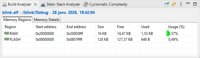
It also shows the amount of memory used by the current project, according to the build report (that is the same information).
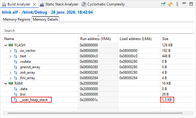
More detailed information is provided in the Memory Details tab. The 1.5kB ._user_heap_stack corresponds to that minimal RAM free space any project must allow, as discussed.
2. Debug session
Make sure that the Nucleo board is connected to the computer and that you have a valid debug configuration. Then start the debugger ![]() .
.
Give a try hitting the resume button ![]() . You should see the green LED flashing.
. You should see the green LED flashing.
Suspend code execution ![]() , and then reset the debugger to the main() entry point
, and then reset the debugger to the main() entry point ![]() :
:
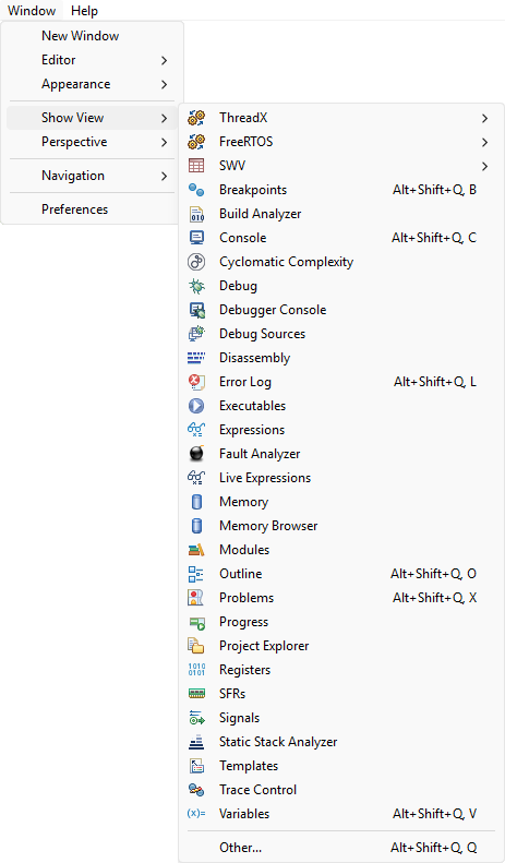
The debugger offers several views of MCU internal state. These views can be opened using the Window →Show View menu:
2.1. Step through disassembly code
One line of C source code usually corresponds to a few lines of assembly code (lower level of CPU instructions). During a debug session, you can step over code lines using the ![]() button. You can toggle whether you want to step over a single C code line or over a single assembly code line using the instruction stepping
button. You can toggle whether you want to step over a single C code line or over a single assembly code line using the instruction stepping ![]() button.
button.
Open the ![]() Disassembly view. It should open on the right side of the main editor, pointing the next machine instruction to be executed.
Disassembly view. It should open on the right side of the main editor, pointing the next machine instruction to be executed.
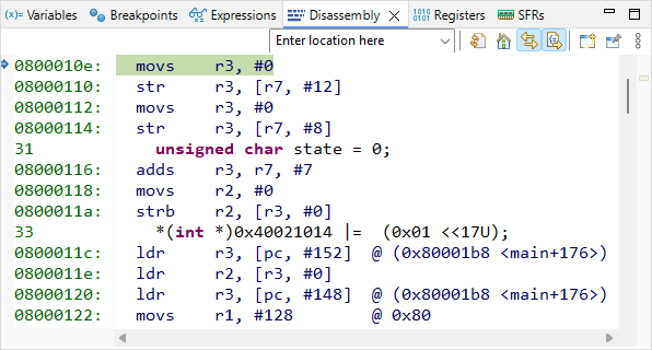
With the instruction stepping mode ![]() being disarmed (off), execute the first line of the C code by pressing the Step-Over button
being disarmed (off), execute the first line of the C code by pressing the Step-Over button ![]() only once and observe the code pointer (arrow) in both C and disassembly window. The first line of the C program corresponds to 4 assembly code lines, therefore it required 4 machine cycles to execute (actually, 2 cycles for each variable (i, j) initialization).
only once and observe the code pointer (arrow) in both C and disassembly window. The first line of the C program corresponds to 4 assembly code lines, therefore it required 4 machine cycles to execute (actually, 2 cycles for each variable (i, j) initialization).
 |  |
| C source | Assembly code |
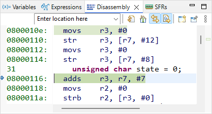
Next 3 assembly lines are supposed to store the value 0 into the memory location corresponding to the variable state. Let us decompose this simple process. To do that, first open the Register view, and display values in Hex format (using the Right-Click contextual menu).
Next toggle the Instruction Stepping Mode by clicking the ![]() button in the main toolbar.
button in the main toolbar.
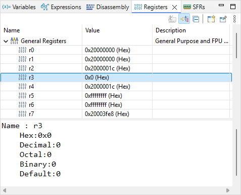
The first assembly line performs adds r3, r7, #7. According to programming manual, this operation takes the content of r7, add the value 7 to this content, and store the result in r3. Open the ![]() Registers view and step over
Registers view and step over ![]() this line.
this line.
Is it doing as expected?
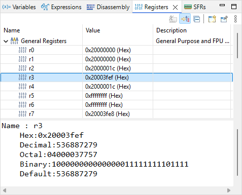
r3 now holds the value 0x20003FEF. This value looks like an address in RAM. It might be the address of the state variable. Let us check that.
Open the ![]() Expressions view. Click
Expressions view. Click ![]() Add new expression and type ‘&state’. The tab now should look like this:
Add new expression and type ‘&state’. The tab now should look like this:
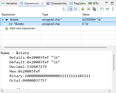
By unfolding &state, you can also see *&state, which is nothing else than the value held by the state variable. The value of &state is the address in memory of the variable state. As expected, it is the same as the content of register r3.
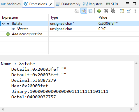
Next assembly line is movs r2, #0. This should reset to 0 the content of r2. Step into the line and observe the Registers view to verify the effect of this line on r2.
Next assembly line is strb r2, [r3, #0]. This instruction stores the content of r2 (i.e. 0) into the memory at address pointed by r3 with an offset 0 (therefore, at the address stored in r3). Note that if state variable is already 0, the line will have no effect.
Then, step-over ![]() one assembly line and make sure state is 0.
one assembly line and make sure state is 0.
For now on, let us stop stepping into disassembly code. Press ![]() again to deactivate the instruction stepping mode. At this moment, your debugger is stopped on the third line of the C program, just before just before some quite obscure initialization.
again to deactivate the instruction stepping mode. At this moment, your debugger is stopped on the third line of the C program, just before just before some quite obscure initialization.
Time for having a look into peripheral registers, and try demystifying this code!
2.2. Monitoring peripheral registers
Open the ![]() SFRs view:
SFRs view:
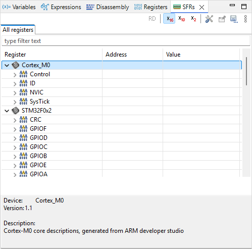
The items listed underneath Cortex_M0 and STM32F0x2 categories are Peripherals. A peripheral is a physical electronic circuit that is designed to accomplish a dedicated task, apart from the CPU code execution. As you can notice, some peripherals belongs to the Cortex-M0 (CPU, designed by ARM®), whereas some others are part of the STM32F0 device (designed by ST®).
Peripherals are configurable circuits. The configuration of a peripheral is done through its Registers.
Under the STM32F0x2 category, unfold the RCC peripheral. This provides access to all RCC registers:
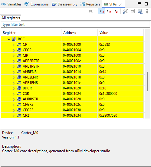
Within a C program, a register is similar to a simple variable which can be read and written. Physically, the memory cells that hold these registers are not located in the RAM, but within the peripheral circuit itself as a bank of flip-flops. That's the main difference. In the STM32, most registers are 32-bit wide (in rare occasions 16-bits or 8-bits), hence manipulated just as any unsigned integer variable.
Before stepping over the next code line, let us think about the meaning of it.
*(int *)0x40021014 |= (0x01 <<17U);(int*) is a pointer, therefore 0x40021014 is an address in memory
*(int *) is then the value that address holds
*(int *)0x40021014 is therefore the value held at register address 0x40021014
|= is a bit-wise logical OR between left and right operands
(0x01 <<17U) corresponds to the value ‘1’ shifted toward the left by 17 bits
The int type represents 32-bit integers :
0x01 = 0x00000001 =
| n | 31 | 30 | 29 | 28 | 27 | 26 | 25 | 24 | 23 | 22 | 21 | 20 | 19 | 18 | 17 | 16 | 15 | 14 | 13 | 12 | 11 | 10 | 9 | 8 | 7 | 6 | 5 | 4 | 3 | 2 | 1 | 0 |
| 0x | 0 | 0 | 0 | 0 | 0 | 0 | 0 | 1 | ||||||||||||||||||||||||
| 0 | 0 | 0 | 0 | 0 | 0 | 0 | 0 | 0 | 0 | 0 | 0 | 0 | 0 | 0 | 0 | 0 | 0 | 0 | 0 | 0 | 0 | 0 | 0 | 0 | 0 | 0 | 0 | 0 | 0 | 0 | 1 | |
(0x01 <<17U) =
| n | 31 | 30 | 29 | 28 | 27 | 26 | 25 | 24 | 23 | 22 | 21 | 20 | 19 | 18 | 17 | 16 | 15 | 14 | 13 | 12 | 11 | 10 | 9 | 8 | 7 | 6 | 5 | 4 | 3 | 2 | 1 | 0 |
| 0x | 0 | 0 | 0 | 2 | 0 | 0 | 0 | 0 | ||||||||||||||||||||||||
| 0 | 0 | 0 | 0 | 0 | 0 | 0 | 0 | 0 | 0 | 0 | 0 | 0 | 0 | 1 | 0 | 0 | 0 | 0 | 0 | 0 | 0 | 0 | 0 | 0 | 0 | 0 | 0 | 0 | 0 | 0 | 0 | |
We don’t know the actual value stored @0x40021014, so let say X can be either 0 or 1 *(int *)0x40021014 =
| n | 31 | 30 | 29 | 28 | 27 | 26 | 25 | 24 | 23 | 22 | 21 | 20 | 19 | 18 | 17 | 16 | 15 | 14 | 13 | 12 | 11 | 10 | 9 | 8 | 7 | 6 | 5 | 4 | 3 | 2 | 1 | 0 |
| 0x | X | X | X | X | X | X | X | X | ||||||||||||||||||||||||
| X | X | X | X | X | X | X | X | X | X | X | X | X | X | X | X | X | X | X | X | X | X | X | X | X | X | X | X | X | X | X | X | |
Given the above, the operation: *(int *)0x40021014 |= (0x01 <<17U) performs the following:
| n | 31 | 30 | 29 | 28 | 27 | 26 | 25 | 24 | 23 | 22 | 21 | 20 | 19 | 18 | 17 | 16 | 15 | 14 | 13 | 12 | 11 | 10 | 9 | 8 | 7 | 6 | 5 | 4 | 3 | 2 | 1 | 0 |
| R= | X | X | X | X | X | X | X | X | X | X | X | X | X | X | X | X | X | X | X | X | X | X | X | X | X | X | X | X | X | X | X | X |
| OR | 0 | 0 | 0 | 0 | 0 | 0 | 0 | 0 | 0 | 0 | 0 | 0 | 0 | 0 | 1 | 0 | 0 | 0 | 0 | 0 | 0 | 0 | 0 | 0 | 0 | 0 | 0 | 0 | 0 | 0 | 0 | 0 |
| R= | X | X | X | X | X | X | X | X | X | X | X | X | X | X | 1 | X | X | X | X | X | X | X | X | X | X | X | X | X | X | X | X | X |
The result being stored at register address 0x40021014
Put in simple words, the operation above does: “set bit number #17 of the register at address 0x40021014 to ‘1’ , and leave other bits as they are”
The value (0x01 <<17U) is called a positive mask in the logical bit-wise OR operation.
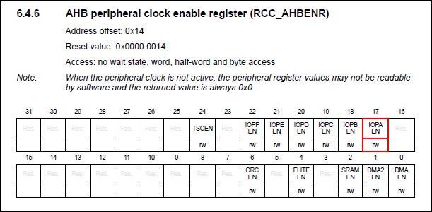
In the ![]() SFRs view, unfold the RCC AHBENR register at address 0x40021014. Then step-over
SFRs view, unfold the RCC AHBENR register at address 0x40021014. Then step-over ![]() once and watch the IOPAEN bit at location 17. It should toggle from 0 to 1. By selecting that particular bit in the SFRs view, you get a short description of what it does.
once and watch the IOPAEN bit at location 17. It should toggle from 0 to 1. By selecting that particular bit in the SFRs view, you get a short description of what it does.
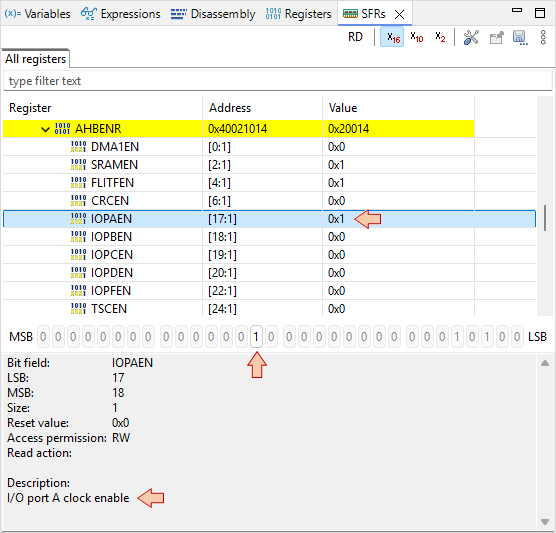
You’ve just turned ON the clock of the General-Purpose Input Output (GPIO) pins associated to the port A (GPIOA). This is done in the Reset and Clock Control (RCC) peripheral.
You can find further information regarding this register in the Reference Manual:
- Why do we actually want to turn in the GPIOA clock?
- That's because this is the GPIO port A that drives the LED.
- How do we know that?
- By looking at the Nucleo board documentation and schematics:
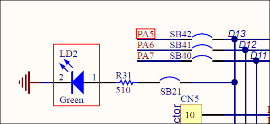
The LED is wired to the PA5 pin of the STM32 MCU. PA5 means "pin #5 of port A".
Next two lines concerns register at address 0x48000000:
*(int *)0x48000000 &= ~(0xC00);
*(int *)0x48000000 |= (0x01 <<10U);
0xC00 = 0x00000C00
| n | 31 | 30 | 29 | 28 | 27 | 26 | 25 | 24 | 23 | 22 | 21 | 20 | 19 | 18 | 17 | 16 | 15 | 14 | 13 | 12 | 11 | 10 | 9 | 8 | 7 | 6 | 5 | 4 | 3 | 2 | 1 | 0 |
| 0x | 0 | 0 | 0 | 0 | 0 | C | 0 | 0 | ||||||||||||||||||||||||
| 0 | 0 | 0 | 0 | 0 | 0 | 0 | 0 | 0 | 0 | 0 | 0 | 0 | 0 | 0 | 0 | 0 | 0 | 0 | 0 | 1 | 1 | 0 | 0 | 0 | 0 | 0 | 0 | 0 | 0 | 0 | 0 | |
| ~ | 1 | 1 | 1 | 1 | 1 | 1 | 1 | 1 | 1 | 1 | 1 | 1 | 1 | 1 | 1 | 1 | 1 | 1 | 1 | 1 | 0 | 0 | 1 | 1 | 1 | 1 | 1 | 1 | 1 | 1 | 1 | 1 |
Then
| n | 31 | 30 | 29 | 28 | 27 | 26 | 25 | 24 | 23 | 22 | 21 | 20 | 19 | 18 | 17 | 16 | 15 | 14 | 13 | 12 | 11 | 10 | 9 | 8 | 7 | 6 | 5 | 4 | 3 | 2 | 1 | 0 |
| R= | X | X | X | X | X | X | X | X | X | X | X | X | X | X | X | X | X | X | X | X | X | X | X | X | X | X | X | X | X | X | X | X |
| AND | 1 | 1 | 1 | 1 | 1 | 1 | 1 | 1 | 1 | 1 | 1 | 1 | 1 | 1 | 1 | 1 | 1 | 1 | 1 | 1 | 0 | 0 | 1 | 1 | 1 | 1 | 1 | 1 | 1 | 1 | 1 | 1 |
| R= | X | X | X | X | X | X | X | X | X | X | X | X | X | X | X | X | X | X | X | X | 0 | 0 | X | X | X | X | X | X | X | X | X | X |
| OR | 0 | 0 | 0 | 0 | 0 | 0 | 0 | 0 | 0 | 0 | 0 | 0 | 0 | 0 | 0 | 0 | 0 | 0 | 0 | 0 | 0 | 1 | 0 | 0 | 0 | 0 | 0 | 0 | 0 | 0 | 0 | 0 |
| R= | X | X | X | X | X | X | X | X | X | X | X | X | X | X | X | X | X | X | X | X | 0 | 1 | X | X | X | X | X | X | X | X | X | X |
In simple words, the operation is: “set bits [11 10] of register at address 0x48000000 to value ‘01’, leaving other bits as they are.”
Because leaving other bits unchanged requires a OR operation which can only set to '1' unmasked bits, we need first to reset all bits under interest to 0. That’s the purpose of the AND operation using ~(0xC00) as a negative mask.
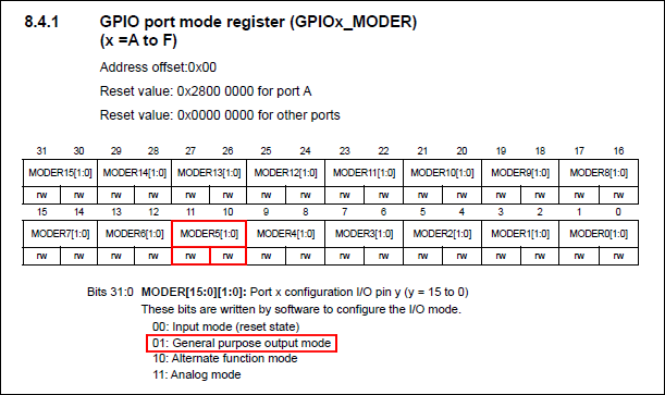
Step-over ![]() the two lines and watch the GPIOA register MODER at address 0x48000000:
the two lines and watch the GPIOA register MODER at address 0x48000000:
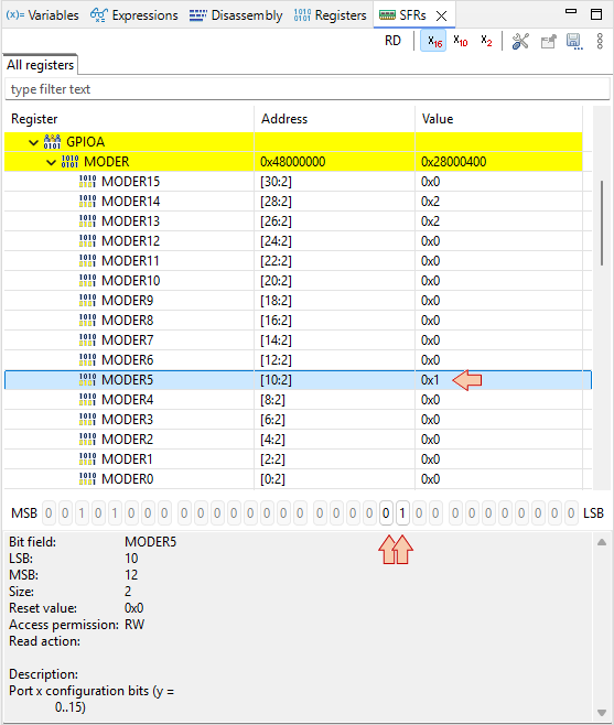
MODER is the register that defines the direction (input/output) of each MCU pins associated with GPIOs. What we’ve just done, is to set PA5 pin as an output. This is precisely what we need, in order to be able to drive the LED.
Note that if the GPIO clock is not started before (as we did), MODER cannot be written. Again, you can refer to Reference Manual to get detailed information regarding the MODER register:
2.3. Monitoring Memory
If everything goes well, the debugger is now stopped at the beginning of the infinite loop:
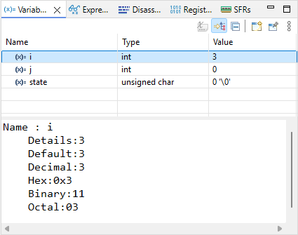
Press ![]() several times to verify that the switch statement behaves as expected (until i=3 for instance). Doing that, observe the values of state, i, j into the
several times to verify that the switch statement behaves as expected (until i=3 for instance). Doing that, observe the values of state, i, j into the ![]() Variables tab.
Variables tab.
Open the ![]() Memory view. Add
Memory view. Add ![]() a monitor &i. The memory viewer then shifts to display the location of i variable first (here at address 0x20003FF4).
a monitor &i. The memory viewer then shifts to display the location of i variable first (here at address 0x20003FF4).
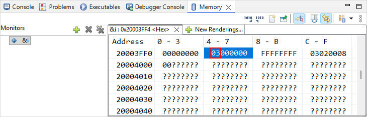
Step over ![]() the code another couple of times to see if the value of i correctly changes in both the Variables and Memory views.
the code another couple of times to see if the value of i correctly changes in both the Variables and Memory views.
Suppose now that we want to check that the switch statement works well when i variable reaches 100000. Obviously, it would take too much time (and pain) to manually step through the code until then.
There are at least 3 ways to achieve this much faster:
Change the value of i to something close to 100000 (eg 99999), in the Variables view
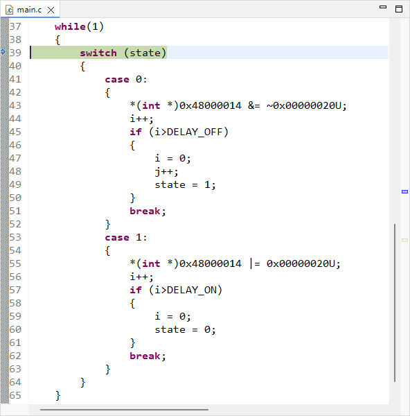
Position editing cursor on line 47 (first instruction when i>100000) and then use Run→Run To Line
 menu command
Set a breakpoint at line 47, and then press the run button

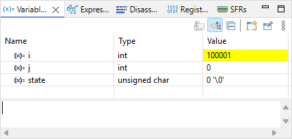
Let-us try the second method. Position editing cursor on line 47 (or the one that corresponds in your source code) and then use Run→Run To Line ![]() menu command. Watch the value of i in the
menu command. Watch the value of i in the ![]() Variables view. Should be 100001 now.
Variables view. Should be 100001 now.
Step-over ![]() the code another couple of times, looking at i, j and state variables and make sure things are behaving as expected (now looping through the state 1).
the code another couple of times, looking at i, j and state variables and make sure things are behaving as expected (now looping through the state 1).
Press the run ![]() button and verify that the LED is blinking in real time, as a normal code execution.
button and verify that the LED is blinking in real time, as a normal code execution.
Note that both ![]() Expressions and
Expressions and ![]() Variables views display variables. So why having both?
Variables views display variables. So why having both?
The
 Variables view automatically displays variables that are local to the function being debugged at a given time. It is not able to display global variables.
The
 Expressions view is where you can display global variables and expressions based on variables.
2.4. Using Breakpoints
Suspend the debugger ![]()
The code line pointer is somewhere in the main loop, depending on when you pressed the pause button. Let us assume that we want to stop the code execution each time there is a change in the LED state. We can do that with breakpoints.
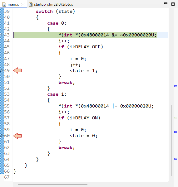
Double-click in the vertical blue lane (on the left of the main editor frame) at line 49 and line 60. You have set two breakpoints, right before LED state changes:
Now the LED state should toggle every time you press ![]() , alternatively stopping program execution on either breakpoints. Note that breakpoints are a limited hardware feature of the MCU. STM32F072 offers up to 4 breakpoints. You cannot set as many breakpoints you want.
, alternatively stopping program execution on either breakpoints. Note that breakpoints are a limited hardware feature of the MCU. STM32F072 offers up to 4 breakpoints. You cannot set as many breakpoints you want.
Info : stm32f0x.cpu: hardware has 4 breakpoints, 2 watchpoints
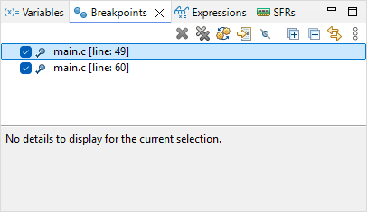
You can view and manage active breakpoints using the Breakpoints view :
We can't leave this tutorial without a look on the two code lines that actually change the LED state, would we ?
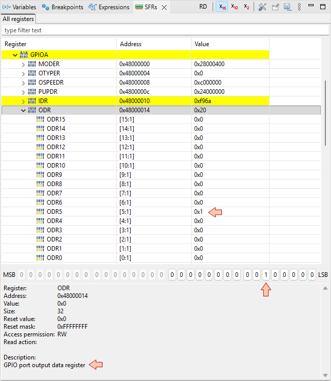
The LED is turned on by:
*(int *)0x48000014 |= 0x00000020U;- 0x00000020 (hex) is equivalent to 0000 0000 0000 0000 0000 0000 0010 0000 (binary). That is a '1' at the 5th position.
- 0x48000014 is the address of the ODR (Output Data Register) register of GPIOA.
So this code simply writes a '1' on bit #5 of the ODR register, of the GPIOA peripheral.
The same way, the LED is turned off by:
*(int *)0x48000014 &= ~0x00000020U;
Well done, you may terminate the debug session ![]() .
.
3. Summary
This tutorial is an overview of the most useful features of the debugger. Debugging is an essential process that you should get familiar with. No new code (even apparently working) should be released without a deep check (line by line) under debugger. You’ll be surprised.
1.2. Hello World (2026)
1.2. Hello World (2026)
In this tutorial, you will create and run the Hello World program of embedded systems which is unsurprisingly : a blinking LED!
Start STM32CubeIDE within your dedicated workspace (workspace_tuto).
1. Creating a new project
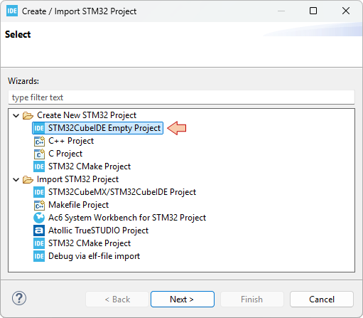
Let us start with a new project STM32CubeIDE empty project. This is achieved by selecting from the main menu: File→STM32 Project Create/Import.
In the Create / Import STM32 Project dialog, select STM32CubeIDE Empty Project.
In the STM32CubeIDE Empty Project dialog, select the MCU you are working with. The Nucleo board that is used all along these tutorials features a STM32F072RBT6 MCU. You'll find it by typing "STM32F072RBTx" in the Mcu Name Filter field. Select the device in the table. Before moving further, it is worth noting that:
The FLASH memory is the non-volatile memory where your program is stored. Its size (128kB) limits the amount of code you can fit into this MCU (i.e. how "big" is your program).
The RAM memory is the volatile memory where program variables live. Its size (16kB) therefore limits the amount of variables your can declare in your program (up to 16000 char, or 4000 int for instance). It is not a lot.
Click Next.
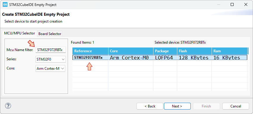
Finally, provide a name for the project "blink", and then click Finish.
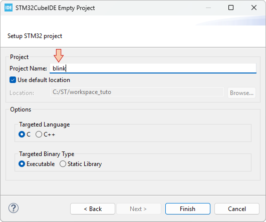
An empty "blink" project is created and added to your workspace. Let us review the folders and files that we have:
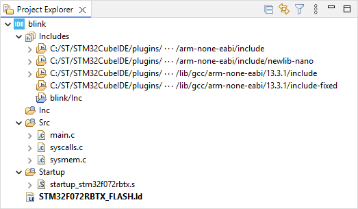
The Includes branch shows all the paths to folders that contains headers (*.h) you might want to include. It concerns gcc standard libraries, and the project header folders. Here we only have one such project folder (blink/Inc), which is by the way empty.
The Inc (for now empty) folder is the suggested place for your application headers (such as a possible main.h for instance).
The Src folder is the suggested place for your application source code (*.c). This is where we find the main.c file that implements the main() function. The two other files (syscalls.c and sysmem.c) are optional, and could be removed by tuning project settings. We'll leave that for later.
The Startup folder contains a single assembly source file startup_stm32f072rbtx.s. That is the piece of code, written by ST, that is executed first, when the MCU gets powered (bootloader). It is a very important code that is in charge of (i) initializing your project variables, (ii) defining the Interrupt Vector Table, and (iii) calling the main() function. For now, the only two things you need to know about this file are :
Any STM32 project must have such a startup code, written for the specific MCU that you are working with.
Do not edit this file.
And finally, something called the LinkerScript: STM32F072RBTX_FLASH.ld. STM32 MCUs have a 32-bit wide address bus. This means that "in theory", up to 232 = 4Gb memory locations are available. As seen earlier, the total amount of memory the device actually features is much less than that. Although there are additional locations such as MCU and peripheral registers to address the total amount of "real" locations is way below 4 Billions. The LinkerScript is the file written by ST that describes the memory layout and in particular, that specifies the address ranges for both the Flash and the Ram memory. It works together with the startup code. For now, what you need to know about that LinkerScript is the same as for the startup code:
Any STM32 project must have such a LinkerScript, written for the specific MCU you are working with, and coming together with the startup code.
Do not edit this file.
2. Edit the main() function
Double-Click the main.c file and locate the implementation of the main() function:
int main(void)
{
    /* Loop forever */
	for(;;);
}
As you can see, the main() function does nothing, looping forever in an empty loop. Note that:
for(;;);Is equivalent to:
while(1);As a matter of fact, it is mandatory for a MCU program that the main() function never returns. So, one way or another, the program is always running within a infinite loop. If you're curious to know what happens if you (accidentally) return from the main() function, take a look in the startup code, right after the call to the main() function. You'll see another forever loop, which is only there as an additional safety net:
/* Call the application's entry point.*/
  bl main

LoopForever:
  b LoopForever
Now, replace the code of the main() function with this one:
int main(void)
{
    int i;

    *(int *)0x40021014 |=  (0x01 <<17U);
    *(int *)0x48000000 &= ~(0xC00);
    *(int *)0x48000000 |=  (0x01 <<10U);

    while(1)
    {
    	*(int *)0x48000014 ^= 0x00000020U;
    	for (i=0; i<100000; i++);
    }
}
It is likely that you don't understand what you've just pasted. Do not worry:
That will be demystified in the next tutorial.
We're not going to keep coding that way for long.
Save all files ![]() .
.
2. Review the Build Settings
At this moment, the project is ready for building. Yet, before we hit the hammer, let us review the project properties to make sure that everything is in place. There are few windows presented next, that you really need to meet (and understand) for future reference.
Right-Click on the ![]() folder and select Properties (or use the top menu Project → Properties, or hit Alt + Enter).
folder and select Properties (or use the top menu Project → Properties, or hit Alt + Enter).
In the left tree view, unfold the C/C++ Build category, and then select the Settings subcategory. In the Settings options, select the Tool Settings tab, and then the MCU Settings folder.
Review the MCU/MPU Settings. If for any reason your target is not there (STM32F072RBTx), you may click the Select... button from the MCU field to pick-up your target part number.
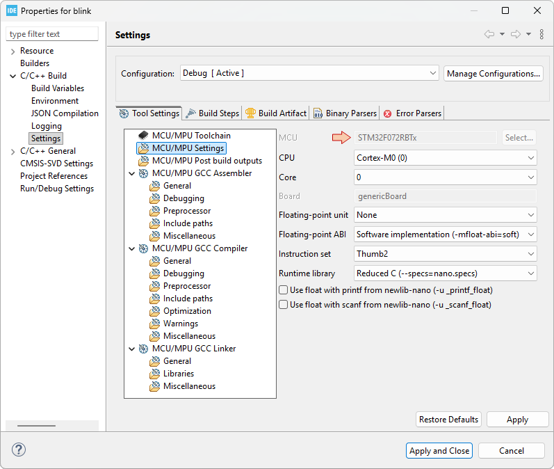
Then, review the Preprocessor page in the MCU/MPU GCC Compiler category. The list in the Define symbols field is used to control source code compilation based on #ifdef, #ifndef, #endif preprocessor directives. Having a symbol defined here is equivalent to write a #define within the source code, but it provides a way to do it without editing generic (library) source files, which is usually a better option. Note that the symbols we have for now (DEBUG, STM32, STM32F0, STM32F072RBTx) are there for future use together with ST libraries that are not included in the project yet. Leave it as it is, but you could remove them all without any issue.
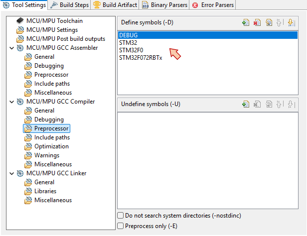
Next, review the Include paths in the same MCU/MPU GCC Compiler category. This is where you can manage the paths to your various headers. It is very important to understand that "just" having a header folder within a project does not tell the builder that it can use it. The folder has to be listed here.
For now, we just have the path to the Inc folder (relative to the Src folder). Again, leave it as it is, but as long as Inc folder is empty, there is no problem removing this entry.
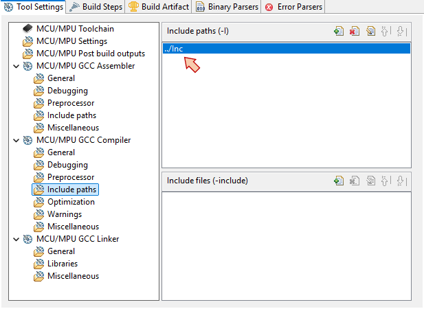
Finally, review the linker options. Still in the Settings subcategory, select MCU/MPU GCC Linker \ General folder and review the Linker Script field. This is where you tell the Linker what LinkerScript to use. If this field is empty, or wrong, you can click the Browse... button and navigate to your LinkerScript file. Wrong path is common when you move project from a computer to another, so you should get used coming here.
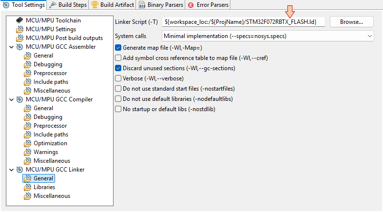
When your done, you can Apply and Close the whole project properties.
3. Build the Project
Hit the build ![]() button, and the project should compile without any error. Make sure you read the build report:
button, and the project should compile without any error. Make sure you read the build report:
17:02:36 **** Build of configuration Debug for project blink ****
make -j22 all
arm-none-eabi-gcc -mcpu=cortex-m0 -g3 -DDEBUG -c -x assembler-with-cpp -MMD -MP -MF"Startup/startup_stm32f072rbtx.d" -MT"Startup/startup_stm32f072rbtx.o" --specs=nano.specs -mfloat-abi=soft -mthumb -o "Startup/startup_stm32f072rbtx.o" "../Startup/startup_stm32f072rbtx.s"
arm-none-eabi-gcc "../Src/main.c" -mcpu=cortex-m0 -std=gnu11 -g3 -c -I../Inc -O0 -ffunction-sections -fdata-sections -Wall -fstack-usage -fcyclomatic-complexity -MMD -MP -MF"Src/main.d" -MT"Src/main.o" --specs=nano.specs -mfloat-abi=soft -mthumb -o "Src/main.o"
arm-none-eabi-gcc "../Src/syscalls.c" -mcpu=cortex-m0 -std=gnu11 -g3 -c -I../Inc -O0 -ffunction-sections -fdata-sections -Wall -fstack-usage -fcyclomatic-complexity -MMD -MP -MF"Src/syscalls.d" -MT"Src/syscalls.o" --specs=nano.specs -mfloat-abi=soft -mthumb -o "Src/syscalls.o"
arm-none-eabi-gcc "../Src/sysmem.c" -mcpu=cortex-m0 -std=gnu11 -g3 -c -I../Inc -O0 -ffunction-sections -fdata-sections -Wall -fstack-usage -fcyclomatic-complexity -MMD -MP -MF"Src/sysmem.d" -MT"Src/sysmem.o" --specs=nano.specs -mfloat-abi=soft -mthumb -o "Src/sysmem.o"
arm-none-eabi-gcc -o "blink.elf" @"objects.list"   -mcpu=cortex-m0 -T"C:\ST\workspace_tuto\blink\STM32F072RBTX_FLASH.ld" --specs=nosys.specs -Wl,-Map="blink.map" -Wl,--gc-sections -static --specs=nano.specs -mfloat-abi=soft -mthumb -Wl,--start-group -lc -lm -Wl,--end-group
Finished building target: blink.elf

arm-none-eabi-size  blink.elf
arm-none-eabi-objdump -h -S blink.elf  > "blink.list"
   text	   data	    bss	    dec	    hex	filename
    560	      0	   1568	   2128	    850	blink.elf
Finished building: default.size.stdout

Finished building: blink.list
17:02:37 Build Finished. 0 errors, 0 warnings. (took 385ms)
There should be no errors or warnings. Note that project structure has been populated with new items:
A Binaries section
A Debug folder
Both contain the blink.elf "executable" file. This .elf file is what you need to run of debug the program onto the Nucleo board:
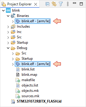
4. Configure the debug session
In the main toolbar, click the dropdown arrow besides the debug button ![]() and select Debug Configurations...:
and select Debug Configurations...:
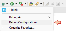
In the Debug Configuration dialog, select STM32 C/C++ Application, and then the New launch configuration button ![]() :
:
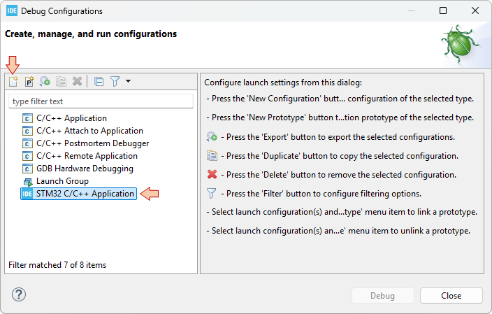
Make sure the new configuration has been created and review parameters in the Main tab:
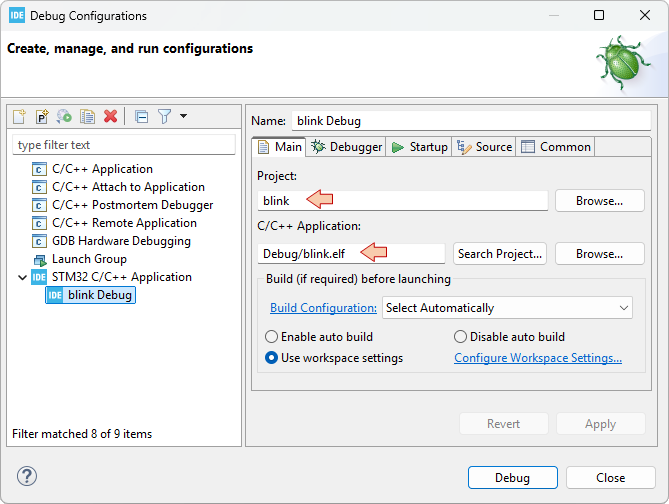
Then move to the Debugger tab and make sure that Debug probe is ST-LINK with SWD Interface:
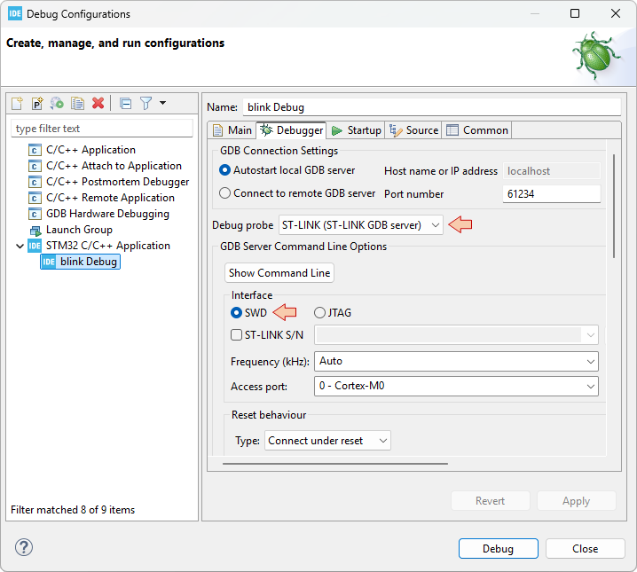
When you've made sure that everything is set, then you can just close the Debug Configurations dialog.
Now, you can either just run ![]() the application on the target, or enter a debug
the application on the target, or enter a debug ![]() session.
session.
5. Run the application
Make sure your Nucleo board is connected, then click the Run button ![]() and watch the STM32CubeIDE console. As you can see, the whole process includes:
and watch the STM32CubeIDE console. As you can see, the whole process includes:
Stating a debug session (gdb).
Downloading (flashing) the program into the target MCU by calling STM32CubeProgrammer.
Closing the debug session.
STMicroelectronics ST-LINK GDB server. Version 7.12.0
Copyright (c) 2025, STMicroelectronics. All rights reserved.

Starting server with the following options:
        Persistent Mode            : Disabled
        Logging Level              : 1
        Listen Port Number         : 61234
        Status Refresh Delay       : 15s
        Verbose Mode               : Disabled
        SWD Debug                  : Enabled
        InitWhile                  : Enabled

Waiting for debugger connection...
Debugger connected
Waiting for debugger connection...
Debugger connected
Waiting for debugger connection...
      -------------------------------------------------------------------
                       STM32CubeProgrammer v2.21.0
      -------------------------------------------------------------------
Log output file:   C:\Users\Laurent\AppData\Local\Temp\STM32CubeProgrammer_a13884.log
ST-LINK SN  : 066DFF544949878667153519
ST-LINK FW  : V2J46M32
Board       : NUCLEO-F072RB
Voltage     : 3.25V
SWD freq    : 4000 KHz
Connect mode: Under Reset
Reset mode  : Hardware reset
Device ID   : 0x448
Revision ID : Rev Z
Device name : STM32F07x
Flash size  : 128 KBytes
Device type : MCU
Device CPU  : Cortex-M0
BL Version  : 0xA1

Opening and parsing file: ST-LINK_GDB_server_a13884.srec

Memory Programming ...
  File          : ST-LINK_GDB_server_a13884.srec
  Size          : 560.00 B
  Address       : 0x08000000

Erasing memory corresponding to segment 0:
Erasing internal memory sector 0
Download in Progress:

File download complete
Time elapsed during download operation: 00:00:00.120

Verifying...
Time elapsed during verifying operation: 00:00:00.003

Download verified successfully

Shutting down...
Exit.
Watch the Nucleo board, you should get the LED blinking:
6. Debug the application
Click the ![]() debug button and watch the console to make sure there's no reported problems. After a little while you should enter the debugger session:
debug button and watch the console to make sure there's no reported problems. After a little while you should enter the debugger session:
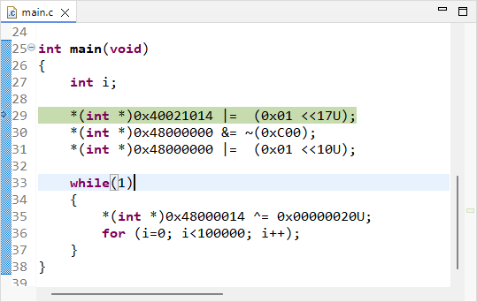
From there, you can control program execution using usual toolbar commands (![]() ,
, ![]() ,
, ![]() ,
, ![]() ,
, ![]() ,
, ![]() , ...).Run the program full-speed by clicking the Resume button
, ...).Run the program full-speed by clicking the Resume button ![]() . You should get the blinking LED as expected.
. You should get the blinking LED as expected.
Note that a debug session runs few processes in the background of your computer. These processes are listed in the Debug frame and include:
The gdb debugger itself, from the MCU ARM GCC toolchain
The ST-Link gdb server for specific access to the Nucleo hardware
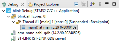
When you're done debugging, that very important that you leave the debugger clean, and these process should terminate automatically. Suspend the debugger ![]() and terminate
and terminate ![]() the debug session and switch back to C/C++ perspective.
the debug session and switch back to C/C++ perspective.
7. Summary
Congratulations, you've got your first STM32 program running.
You've done much more than you think:
You've got all the tools installed.
You've created a project that compiles.
You've configured the build
You've configured the run/debug session
1.1. Tools Setup (2026)
1.1. Tools setup (2026)
To complete these tutorials, you'll need to install the following software on your computer :
 STM32CubeIDE : The Eclipse/gcc based Integrated Development Environment (IDE) officially developed and promoted by ST.
 STM32CubeProgrammer : A standalone software for programming (flashing) STM32 devices. It is also useful to program device Option Bytes (OB) and can also be used to update ST-Link firmware.
 STM32CubeMonitor : A Node-RED based application to monitor live variables and build custom dashboards.
1. STM32CubeIDE

Since 2019, STM32CubeIDE has become the free, STMicroelectronics supported, integrated development environment for STM32 MCUs. It is available for all major OS (Windows, Linux, Mac). By january 2026, ST released the version 2 of STM32CubeIDE introducing several changes in the workflow, including a clear separation with CubeMX tools. Tutorials have been adapted to this new approach, so please be sure to get a version that is ≥ 2.0.0.
You can download STM32CubeIDE from ST website: www.st.com/en/development-tools/stm32cubeide.html. You will be asked to create an ST account prior to the download.
Then just select the installer you need according to your OS:
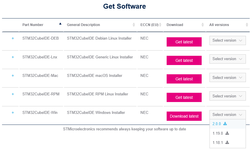
Start the installation process. Keep the installation path short and avoid any special character, accents or spaces. You may for instance choose C:\ST as the installation path as shown below:
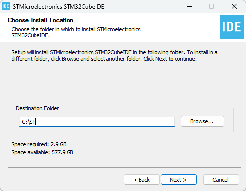
Make sure both J-Link and ST-Link drivers are included in the installation process:
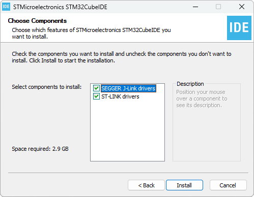
When finished, visit the installation folder and make sure STM32CubeIDE executable is there:
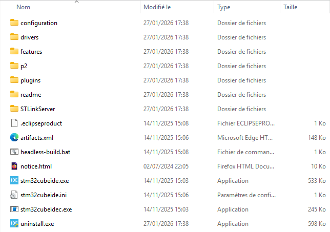
You may then start STM32CubeIDE using your OS launcher :
![]()
- Globally (for all your eclipse tasks)
- At workspace level (for all projects inside a given workspace)
- At project level (for one project only)
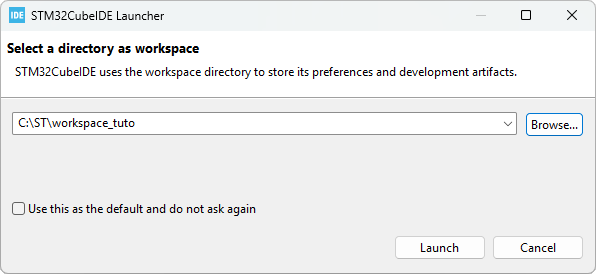
When starting STM32CubeIDE the first time, your network firewall may ask for an authorization that you should accept. An Internet access is required for updates, and device-related libraries downloads.
You may also be asked for automatic data collection from ST in order to improve the product. That's up to you to accept or deny this one.
When STM32CubeIDE has finished loading, you'll end-up within Eclipse. Close the Information Center.

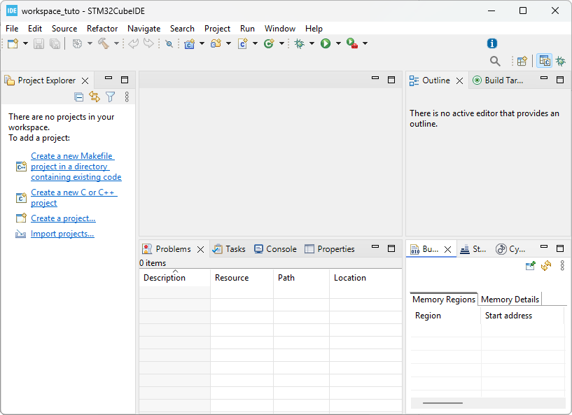
2. Testing ST-Link drivers and Nucleo board
Because STM32CubeIDE comes with ST-Link drivers, you should now be able to connect the Nucleo board to your computer using the USB cable.
For now, do not pay attention to the LEDs on the Nucleo board. Plugging the USB cable should first attach a new drive to your computer:
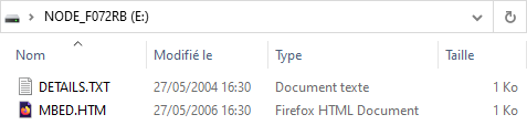
Note that this is a fake drive, that is only provided as a mean to flash the target device by drag and dropping executable files prior downloaded from the online MBED environment. It is by no means a mass storage device that you can use for storing files. Actually, it will be of no use for us since we're not using MBED.
Then visiting the Windows Device Manager, you should see two new items:
The ST-Link Debug probe under USB Peripherals category
An ST-Link Virtual COM Port under the Ports category
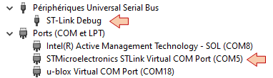
If you can't see those, then there is no need to go further. Something went wrong with the installation process, or your Nucleo board is not working properly. Review the above instructions and try again.
3. STM32CubeProgrammer

You can download the STM32CubeProgrammer from ST website: www.st.com/en/development-tools/stm32cubeprog.html.
Proceed to the installation. You can use the same installation folder as for STM32CubeIDE (eg C:\ST\STM32CubeProgrammer):
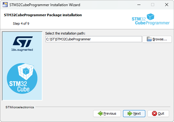
Then accept default options:
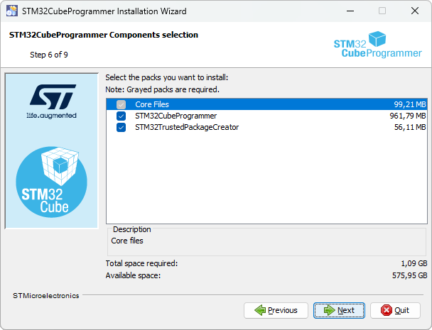
When finished, unplug the Nucleo USB cable (if plugged) and launch STM32CubeProgrammer using your OS:
![]()
STM32CubeProgrammer should then signal that no ST-Link is found:
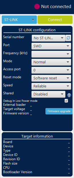
Then, connect the Nucleo USB cable and hit the refresh ![]() button. Now the ST-Link debug probe is found.
button. Now the ST-Link debug probe is found.
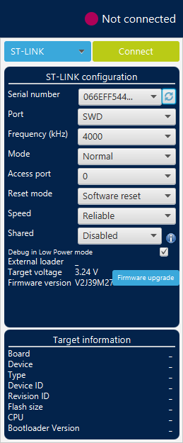
Before connecting to the target STM32, let us see if the ST-Link requires a firmware update.
Hit the ![]() button.
button.
In the STLinkUpgrade dialog box, click the Open in update mode button first. ST-Link will be briefly disconnected/reconnected and update information appears in the lower part of the window. If this doesn't work, you'll have to power cycle (unplug/plug the USB cable) the Nucleo board and click the Open in update mode button again.
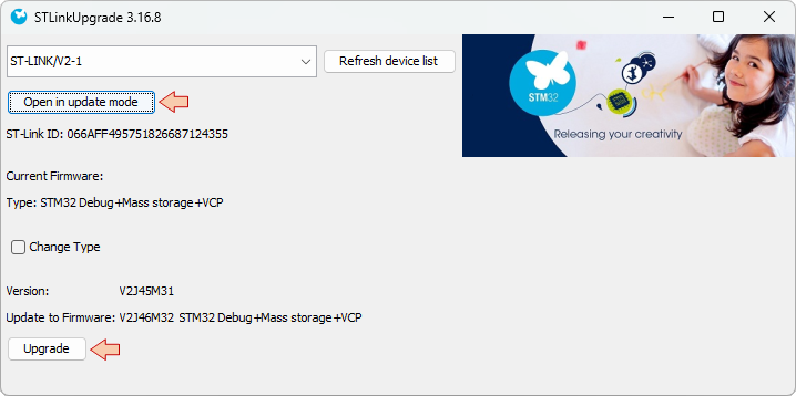
Then click the Upgrade button and wait until the process complete. A message tells you that the process is successful. Make sure to close this dialog before proceeding to next step.
Now click the ![]() button
button
Make sure that the status changed to "Connected":

Then review the Target information region. This one should report the found target board and device:
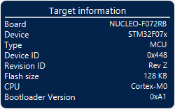
Also review the Log area which reports useful information gathered while connecting to the target:
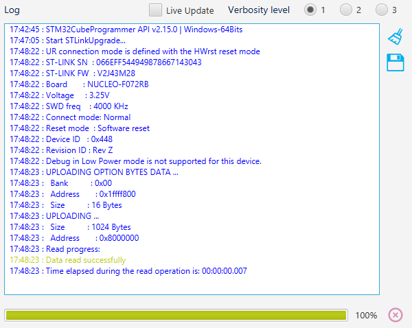
If everything went as expected, you can now feel confident that all is working properly and that you have an up-to-date ST-Link.
IMPORTANT WARNING: Within STM32CubeProgrammer, you can access Option Bytes (OB) and change the memory Read Out and Write protection level. DO NOT TRY ANYTHING HERE unless instructed. Changing the memory protection level is an irreversible action that will definitely brick your Nucleo board and is intended for mass production and intellectual property protection.
If you memory-protect your development board, then you can keep it as a decorative fashion accessory. Yet, too big for earrings...
You've been warned...
Click the Disconnect button, and close STM32CubeProgrammer.
![]()
4. STM32CubeMonitor

Last in the list is the STM32CubeMonitor tool.
It is available for download from ST web site : www.st.com/en/development-tools/stm32cubemonitor.html
Again, use the same folder as before for the installation location (eg. C:\ST\STM32CubeMonitor):
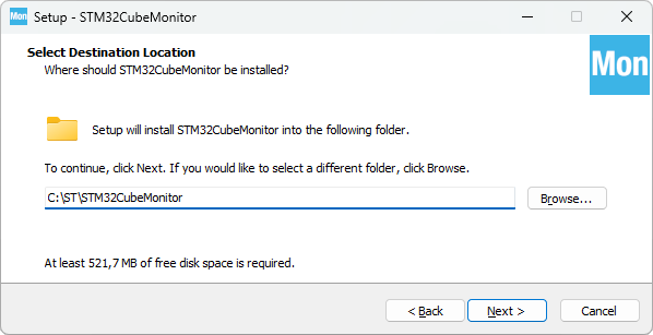
Then complete the installation process.
When done, just make sure that STM32CubeMonitor launches without problems:![]()
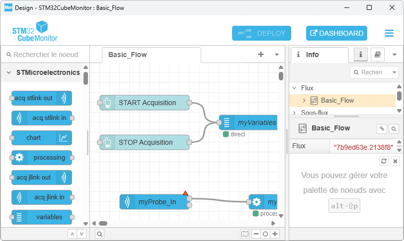
Then quit the application for now. We'll leave this for another tutorial when required.
5. Summary
In this tutorial, we've set up all the software tools you'll need to proceed with the subsequent STM32 training program. If you've followed above instructions well, you've got a directory with a short and simple path from the root that regroups :
3 development tools:
The Integrated Development Environment (IDE), which is the place you write programs, build executables and perform debugging tasks.
A standalone programmer tool, useful to check that ST-Link and target board are healthy, and necessary to perform low-level configuration.
A tool to monitor live variables at runtime and build custom dashboard. You must consider this as another (complementary) debug approach to the standard debugging process. It is particularly useful during optimization of real time control projects and more generally with projects that involve signal processing.
1 workspace folder to store tutorials projects.
Welcome
Welcome to PoMAD
PoMAD is a platform created to publish MCU tutorials and educational projects.

This work is licensed under a
Creative Commons Attribution-NonCommercial-ShareAlike 4.0 International License.
This license lets you freely remix, adapt, and build upon this work non-commercially,
as long as you credit this site, and license your new creations under the identical terms.


About the Author: Laurent Latorre is Professor at University of Montpellier, France, in the field of Electrical Engineering and Embedded Systems. The tutorials are currently used as teaching materials at Polytech Montpellier.


Credits
Throughout the years of this website's existence, many students have contributed to improve these tutorials, either by providing feedback while practicing programming, or by reporting typos and helping to improve the writing. Thank you so much.
I am especially grateful to:
- Malin Lundmark (2025)
- Adrien Kerfriden (2025)
- Lucas Musumeci (2025)
- Bilel Zakani (2025)
- Adam Mabrouque (2025)
- Aymeric Duchene (2025)
- Mathis Escofet (2025)
- Etienne Guigon (2023)
- Richard Trieu (2022)
- Cyril Fernandez-Bourgadieu (2020)